An alternative power supply for the Wireless Set No. 62.
By Keith Watt RN (Rtd.)
This regulated inverter will both power the WS62 and will fit in place of
the
original internal dynamotor should your original have failed.
The original dynamotors were only rated at some 500 hours use before expected
failure!
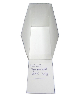
The start of the project was to ensure that the PCBs that the inverter and
the regulator
would actually fit within the confines of the original box the dynamotor fits
in side of.
A crude card box was made the same size as the dynamotor's box so that PCBs
could be
fitted within and checked for clearances etc.
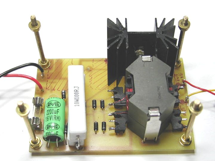
The PCBs were cut and fastened together with 4BA brass rods;
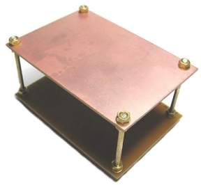
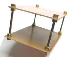
Then checked that they fitted within the box;
Complete circuit diagram of the inverter and regulator.
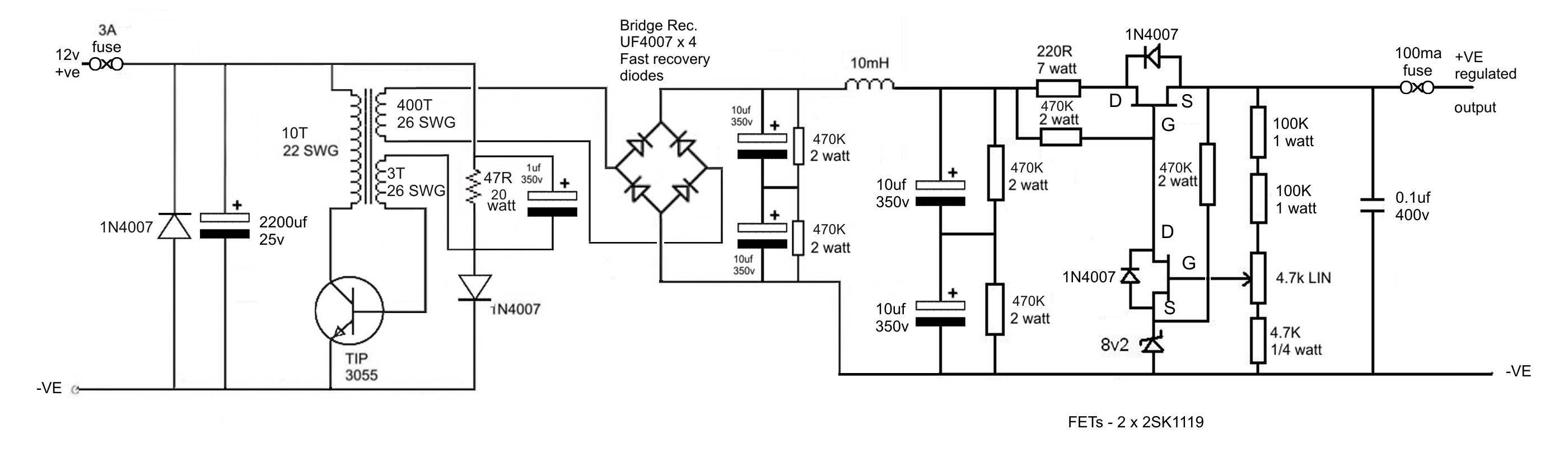
Click on image for larger view of circuit layout
Breadboard prototype testing was undertaken to ensure values, heat sinks
and ratings were within tolerances.
A few minor changes have been made to reduce generated heat and current consumption.
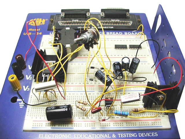
A "rat's next" but it works well for testing and proving things
are what they should be before
committing to PCB design.
The regulator section was built first.
PCB was drawn up, etched and drilled by hand;
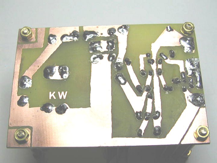
The pads around the mounting posts can be soldered over to the ground on the
PCB to make a common ground
between the 12 volt input and the HT output. As it is with the posts isolated,
the output of the PSU is floating
enabling it to power any kind of valve radio within its output capabilities.
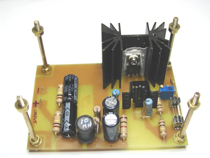
After testing to confirm it works to specification, the inverter sections was constructed;
The transformer was hand wound;
Half the secondary was wound on first, some 200 turns of 26 SWG, then the
primary is wound on, 10 turns of 22 SWG,
then the remaining 200 turns of the secondary is wound on, followed by the
3 turns of 26 SWG for the feedback winding.
[1] The transformer core is a RM14 with a 0.3 mm air gap (I placed a piece
of card between the two halves of the ferrite core).
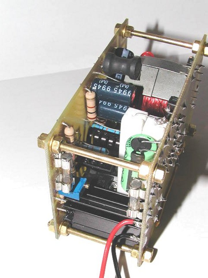
The PCBs were designed to stack one of top of the other to make it an easy fit within a WS62 Dynamotor box.
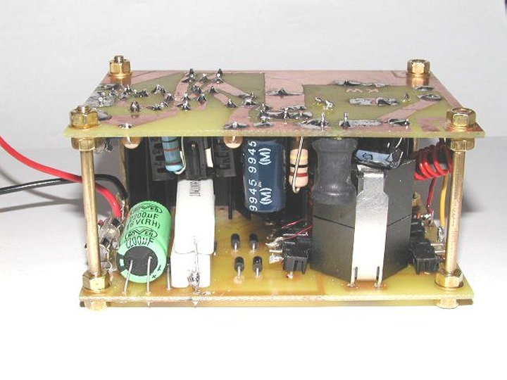
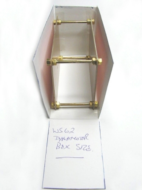
A look around the now finished PSU;
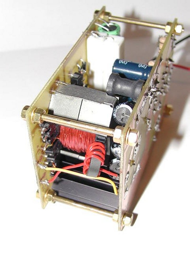
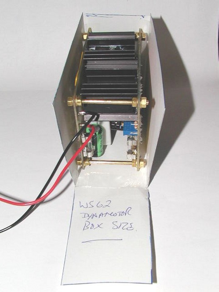
The card box that is the same size as a WS62 Dynamotor box was again used
to confirm that the PSU
will still fit within the confines of the box;
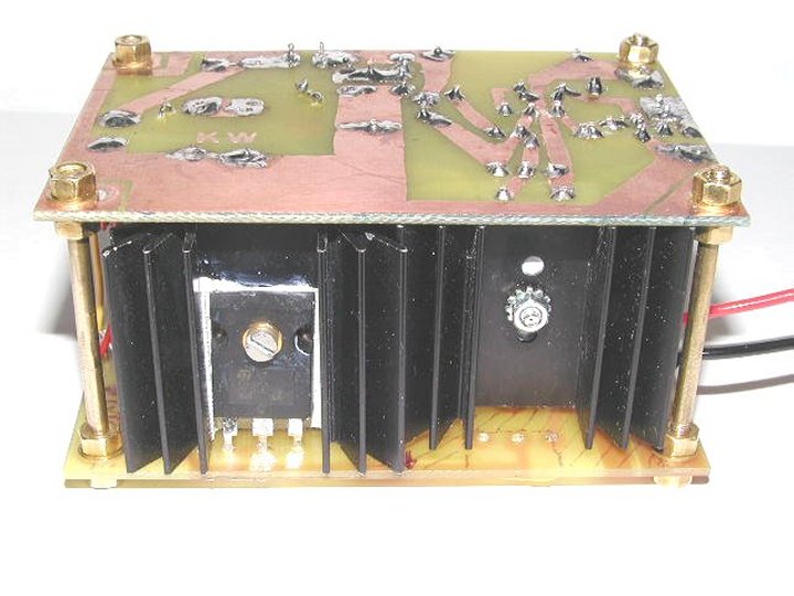
The inverter transistor and regulator pass transistor would both greatly
benefit from being mounted on the Dynamotor case
to reduce the heat should this PSU be used to power a WS62 in place of the
original Dynamotor, as it is on the enclosed
heat sink it does get hot on load.
The next step in the evolution of inverters - http://www.xkcd.com/730/
It should be noted that this power supply has an adjustable output of 90
volts to 350 volts at a load of up to 80 ma.
So it is capable of powering a great deal more types of radio than just a
WS62.
[1] RM14 Transformer cores are available from;
SDA Electronics Ltd,
Unit 30 Willan Industrial Estate,
Eccles New Road,
Salford,
M50 2GR,
UK.