The
Wireless-Set-No19 Group |
Restoration of R209 Mk1, M.B.L.E.
:
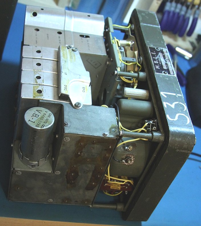
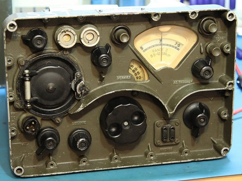 I received this little R209 sometime in the winter of 2018/2019 from a fellow in the Netherlands. At the time I was thoroughly distracted by other projects and the radio sat in the box for a month or two before I finally opened it. Being a MK1 version, this unit is wired for 6 volts. It came with the proper power cord and I hooked it up to a suitable power supply for its initial test. I was assured when I bought it that it was working and I was not lied to. Sure enough the set came to life right away. After using the set for a few days, the issues became apparent. Reception was not stable for some reason. This was only really noticeable when the BFO was on. There was some shifting in the CW notes and such. Another problem was the audio output. It was quite low compared to my MK2 versions. At times, something would happen in the radio to cause it to drop so low that I could barely hear it with the gain turned all the way up. Clearly some problems had to be dealt with before I could fully enjoy using the receiver.
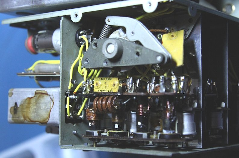
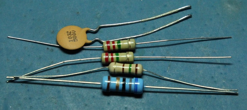
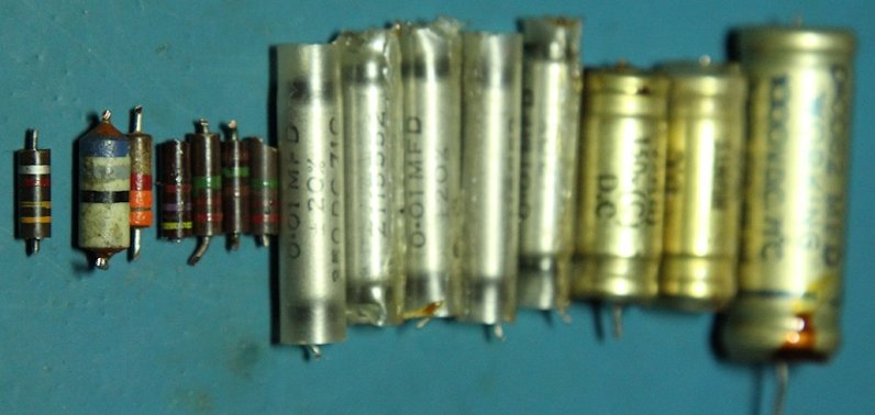
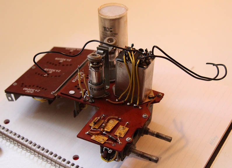
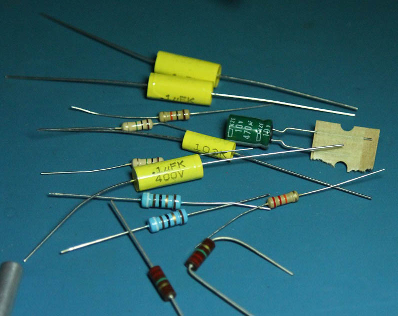
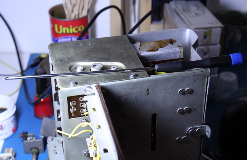
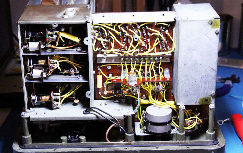
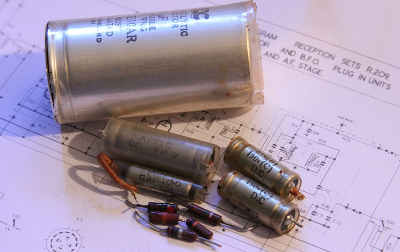
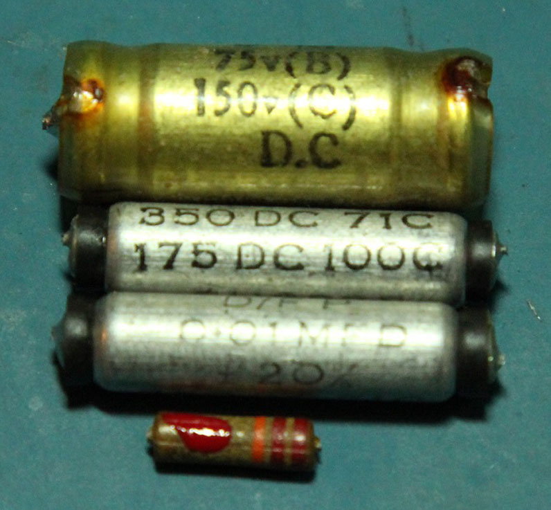
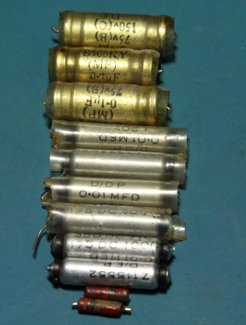
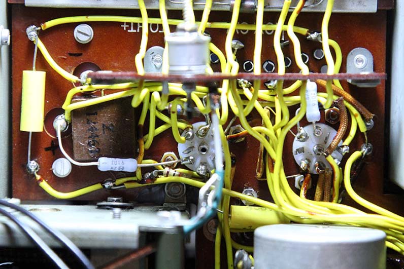
I had the receiver taken out of its case since the day I took it out of the box. It wasn't long before I was poking around inside. At some point I traced the instability to dirty contacts in the band switch. Some deoxit seemed to solve that problem, but the radio still had issues. On occasion the speaker would fly into a fit of crackling and buzzing that made me uncomfortable. This as well as the random drops in volume that lasted anywhere from five seconds to ten minutes, this convinced me to proceed with an in depth electrical restoration. 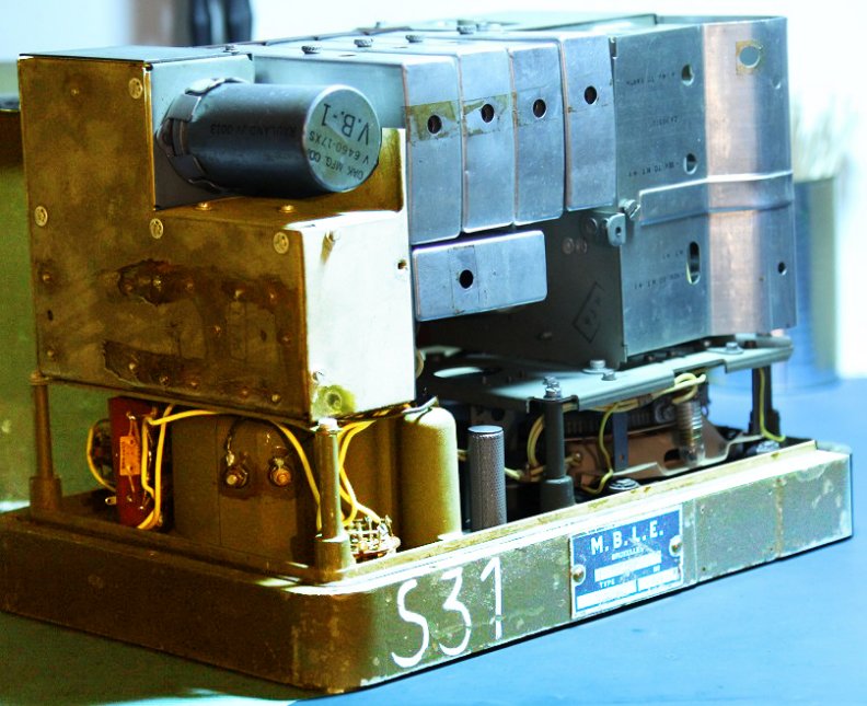 I figured that the power supply was a good place to start. Sorting out any issues there first could narrow down other problems. The B+ voltage prior to working on the power supply was measured around 87 volts. I removed the six screws holding the power supply in place and cut the wires leading to it. There are two wires for the 6 volt input and two wires for the B+ and A+ output. The power supply of the MK1 differs from that of the MK2 in that the vibrator is not covered by the metal shield. This makes it easier to replace the vibrator, but in order to remove the shield for servicing the power supply, the power supply must be disconnected and removed entirely. I removed the cover of the power supply after getting it out and the first thing I noticed was a wire with melted insulation. 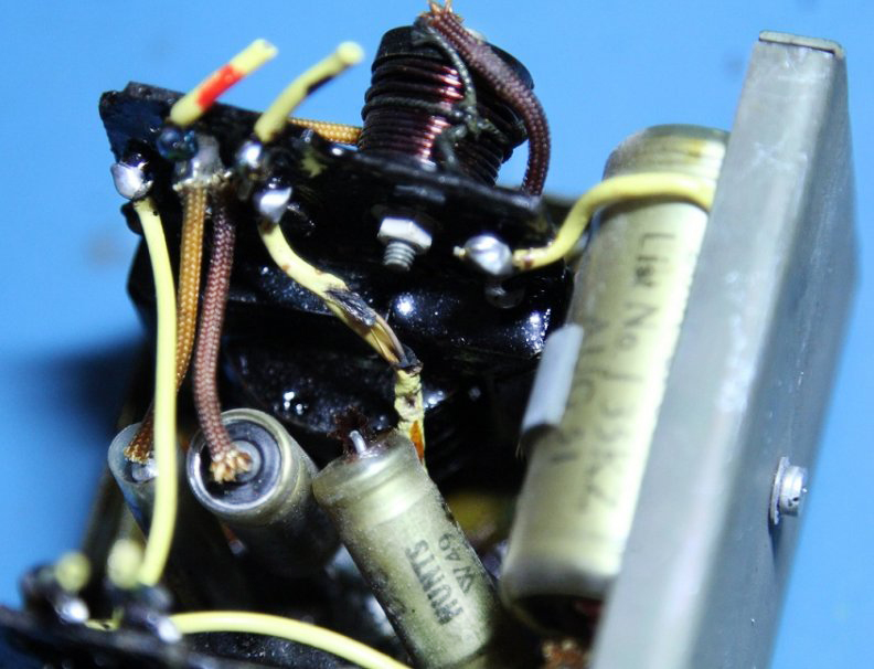 This wire turned out to be the -6 volt input. It goes from the input terminal to ground. It does appear to be a rather thin wire in the first place. But perhaps something happened that caused the radio to draw more current than usual and thus melting the insulation on the wire. As well as the melted wire insulation, there were plenty of old capacitors. The radio worked decently, so they were probably not too far gone, but I've never been one to take chances. I looked up the values of the capacitors I would need and got them together for the recap job. I did not have any 8uf 150v caps so I used 10uf 160 volt ones. I also did not have any .0082uf caps at 1500v so I left that capacitor in place for the time being. 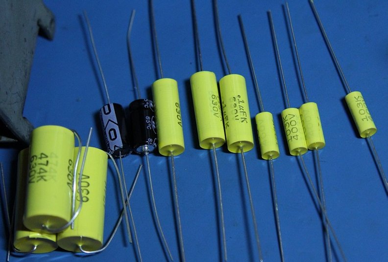 I neglected to take any pictures of the power supply before I began the recapping process. I started with the section under the vibrator. There were three 0.01uf caps and two 0.47uf caps as well as two 1 ohm resistors that tested good. Once that section was done, I moved on to the rest of it. I replaced the two 8uf caps, another 0.01uf, and three 0.1uf caps. 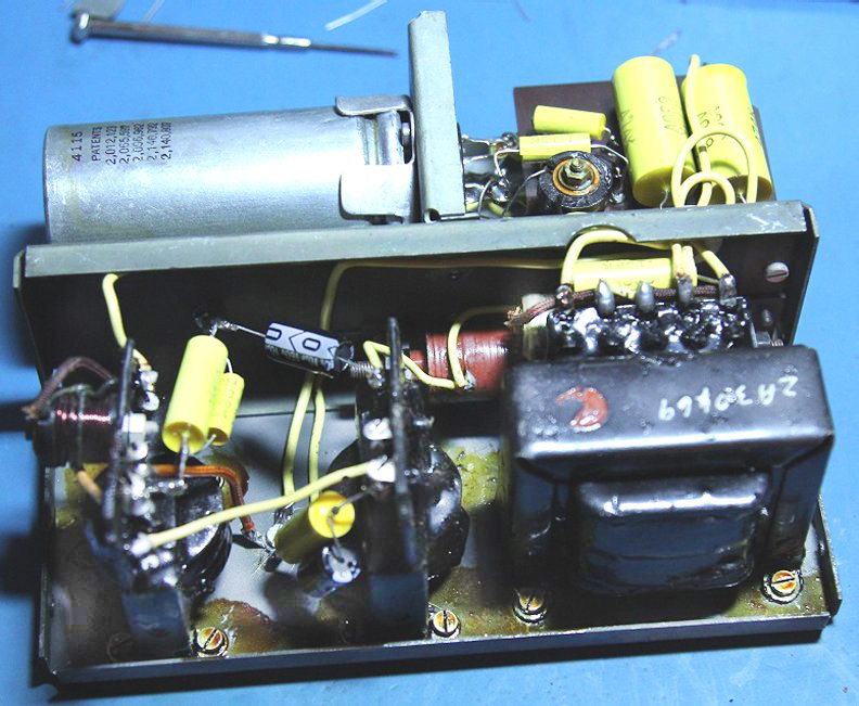 Next I tested the power supply by wiring it up with clip leads. The B+ output under no load was 160 volts. Under load it dropped to around 100 volts yet the radio did not work. The voltage regulator neon would light at first then go out. I found that by increasing the input voltage from 6 volts to around 6.3 got the radio to work somewhat. Sill the neon regulator would go out though. The BFO was also not working. I put the cover back on, reinstalled the power supply and tested the radio again, same thing. I was still using clip leads to feed power from the switch to the power supply. They were quite small and I thought that perhaps they were current limiting the input voltage. I swapped them for thicker leads and the radio then worked properly. At least as well as it did before. Below are the 12 capacitors I replaced out of the 13 in the power supply. You can see a date code of August 51 on the larger caps. This is the first indication of the age of this receiver that I have found. 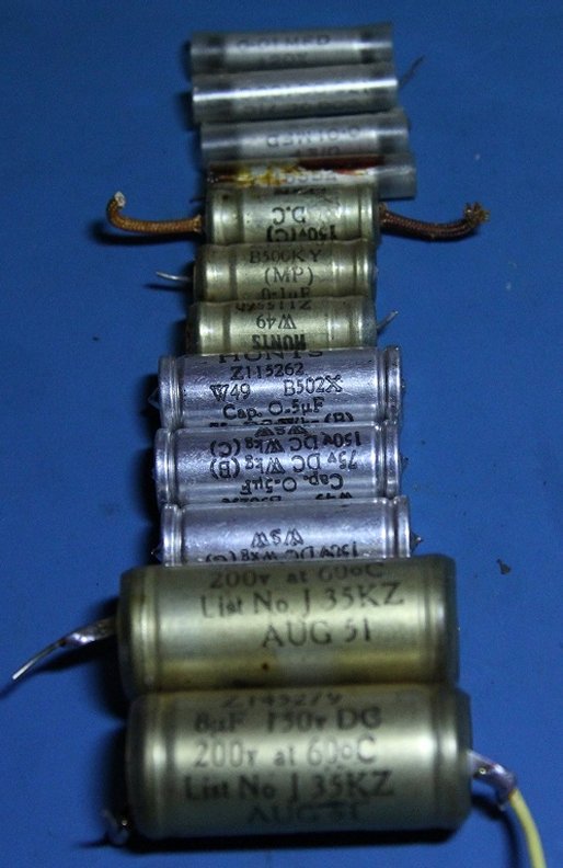 With the power supply section mostly finished and a few parts left over to do another section, my focus shifted to the front end of the receiver, starting with the switch assembly. Most of the components for the RF, LO, and Mixer tubes/valves are above the chassis on a tag board. However, there are a few components inside the switch assembly that must be inspected. This is the most challenging part in my opinion. Whether you wish to disassemble it for easier access to the components to be replaced, or simply work in the tight corners as I did, it's not an easy task. Removal of the bottom plate with the modification table provides access to the band switch assembly. : Going a step further and removing the rear plate that supports the switch mechanism can give more room to work, at least, on the rear most section. It also allows more light to be shed on the work area.
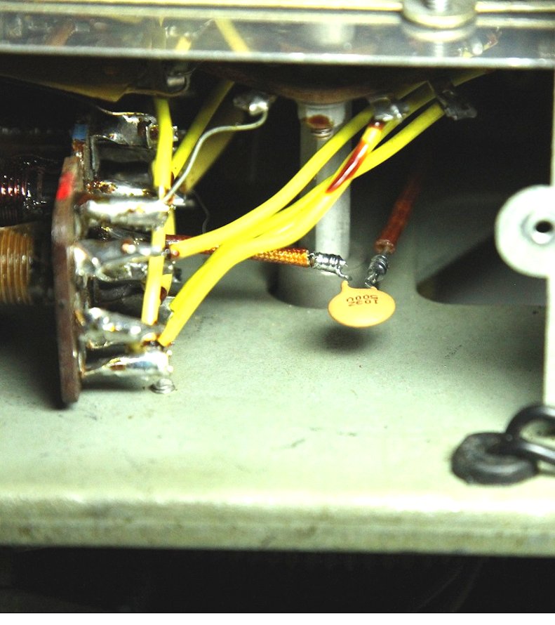
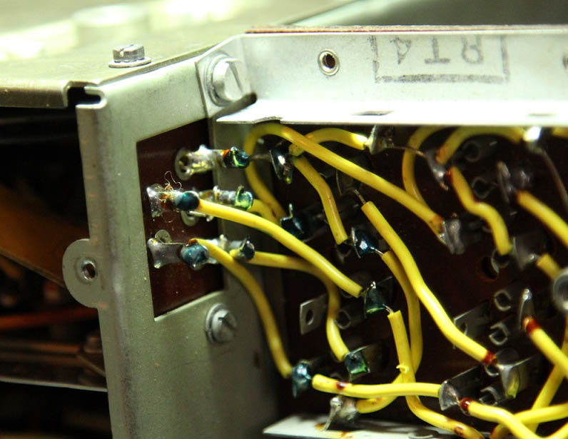
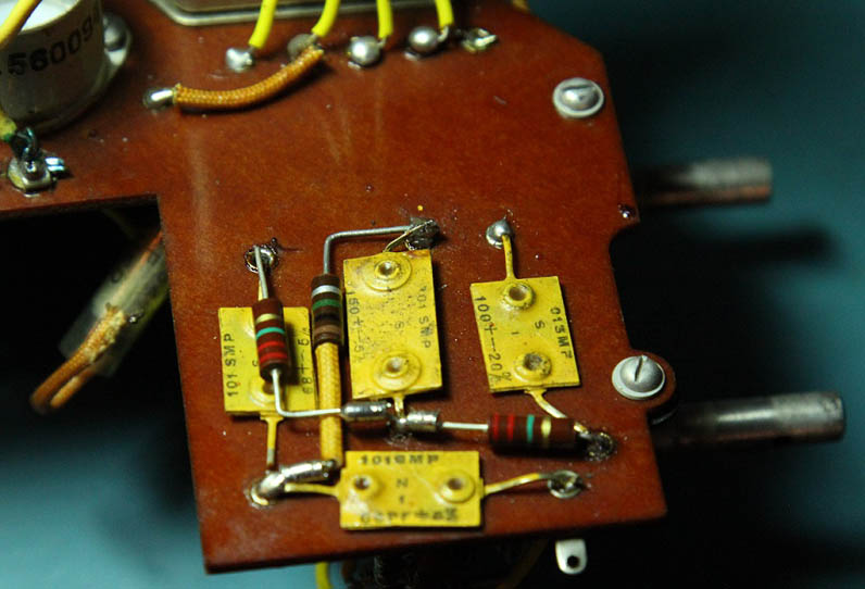
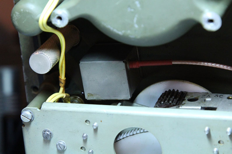
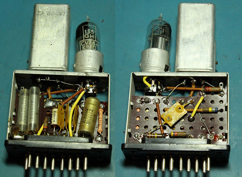
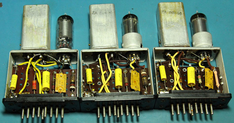
Most modern meter probes have a safety ring around them to prevent them from slipping in one's hand. My probes were too large to fit into the tight sections to test component values, so I used an old set as can be seen in the first picture of the switch assembly. I went through the switch section and tested all the resistors. The 33K in the oscillator section tested within 3% of value. I was relieved as it is the most buried and would be next to impossible to replace in the same position. The other four resistors were not so close. The worst of which being around 40% out of spec! I gathered replacements for the resistors as well as one capacitor. The capacitor to be replaced is a .0082uf 1000v rated tubular capacitor. I decided to replace it with a .01uf capacitor as I did not have any .0082uf in that voltage range. I don't think the voltage needs to be that high in most cases, but some larger antennas can build up quite a charge on them. I figured a 500v ceramic disk was a reasonable choice. : It took me about two hours to replace these five components to my satisfaction. I'm not going to describe it in detail as that may take even longer than the process did! I'm just going to offer some suggestions. A long soldering iron tip is a must! The components that must be replaced are around three inches deep in the switch assembly, nestled between wires and other components. Good lighting is also necessary. A head lamp would be a good choice, although I bought my good one a week after this section, go figure. Long reach tools are necessary. Needle nose pliers with long handles, long reach wire cutters, hemostats, tweezers, screw drivers, butter knife, rusty scissors, trust me, I used them all! The most important tools of all for this section and this radio in general is patience and ingenuity! Below are some pictures showing the section after replacing these five components, not that it's easy to see them though.
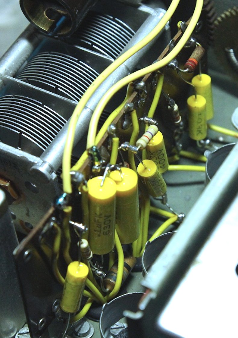
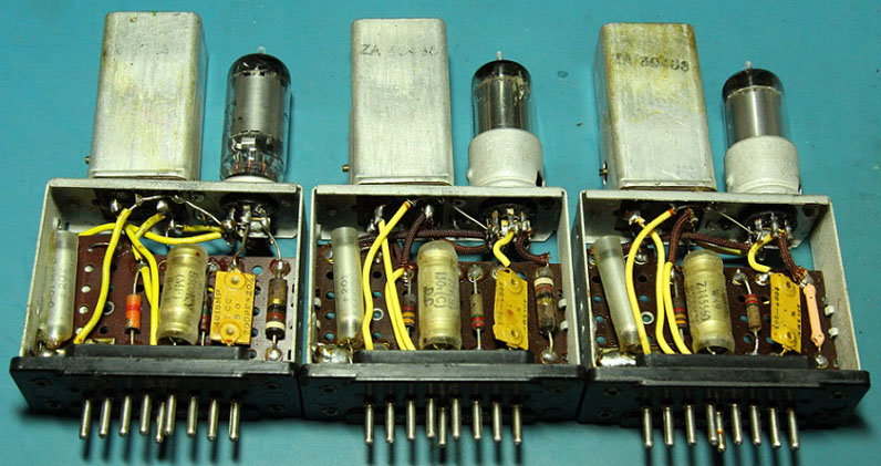
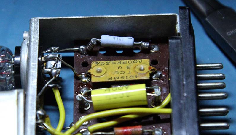
With the switch section of the front end finished, I tested the radio and moved on to the top side. All the components to be replaced here are mounted on a tag board between the tubes/valves and the variable capacitor. There are seven capacitors and nine resistors on this board.
I tested all the resistors and found three out of spec ones, the worst again being around 40% out of spec. This particular resistor was a 4.7K that had unusual colors. Instead of being Yellow/Violet/Red, it was quite obviously Yellow/Yellow/Red. I double checked the schematic and parts list to confirm that it was indeed supposed to be 4.7K resistor. I gathered the three replacement resistors and seven capacitors and got to work replacing them.
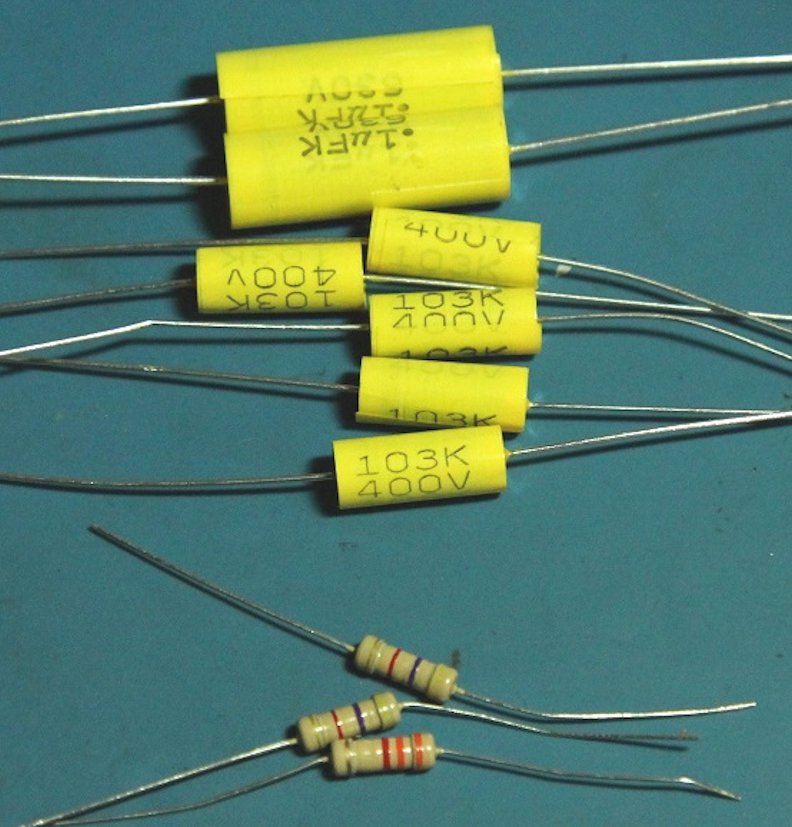
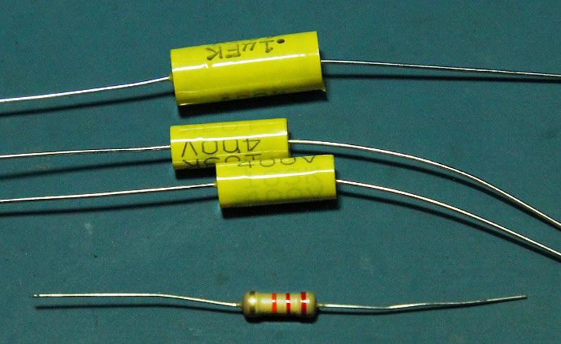
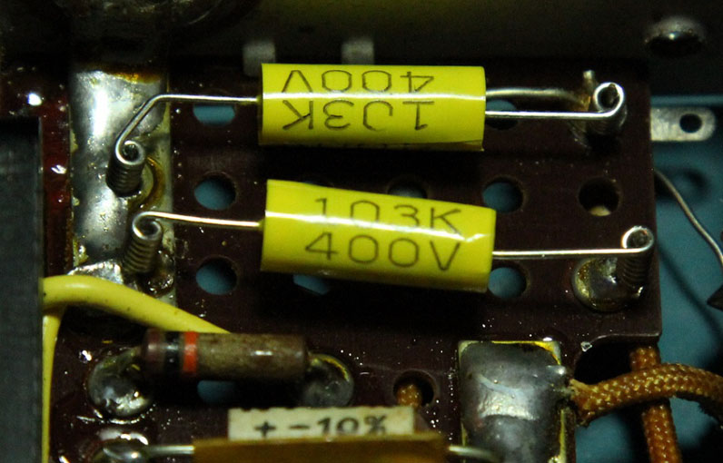
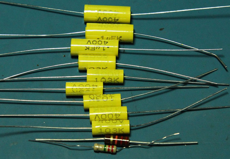
This section is not as tight as the switch assembly, especially when the tubes/valves are removed. This section took about half an hour to complete. Still care must be taken to avoid shorts and such in the relatively small space as well as avoiding melting wire insulation with the soldering iron tip. I use spaghetti tubing where required to ensure that parts will not short even if vibration or shock causes them to shift in position. The capacitors I am using are generic 400 and 630 volt polyester film capacitors and they have thick, sturdy leads which help keep them secure once soldered in. The photo below shows the section after completion.
Below are the components that were replaced from these sections. You can see the mysterious discolored 4.7K resistor I mentioned earlier at the end there.
With the front end section components checked and replaced accordingly, I tested the radio again. Sensitivity seems better than it was before but obvious issues remain. The instability that I thought I had rectified by cleaning the band switch seemed to have returned a while back and it was still there when testing again. I found that tapping the BFO knob shifts the frequency, leading me to believe that the variable capacitor in there is dirty. I will have to inspect that in the future.
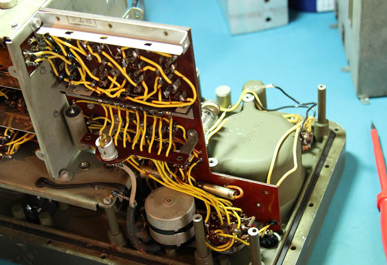
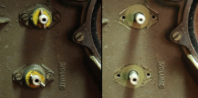
This section along with the mode switch and gain potentiometer stack is removed in one piece. First the power supply is removed, then the knobs, pins, felt washers, and gasket assemblies for the two controls. After that, there are six screws remaining holding this section in place. There is also a seventh screw that screws to the power supply section.
The image above shows the control shafts with the knobs removed on the left and the pins, felt washers, and gasket assemblies removed on the right. The knobs are each held on with a screw threaded into the shaft and the pins interface with a divot molded into the rear side of the knobs. With the control knob assemblies and screws removed, the terminal board section is now loose. In order to remove it, the three audio wires (one to the speaker and two to the headphone socket) must be detached as well as five wires connecting to the RF section and the coax running to the BFO control. Of course the first wires to be removed are the two connecting to the power supply prior to its removal. Below is a close up shot of the five wires connecting to the RF section and one of the BFO control coax. : With all that done, I lifted the section out of place carefully. There was a small break in the phenolic board with two small pieces that I did not want to lose. I had noticed this break before and knew it would be a pain to deal with. I've highlighted it in the picture below.
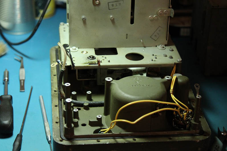
With the terminal board section removed, the chassis looks rather bare. The majority of the work on this section can be done without removing it from the chassis, but I much prefer doing it this way.
I gathered up the necessary components for this section after testing resistors and looking up capacitor values. I still find the layout of the parts sections in the manual a bit confusing. Sometimes two parts just an inch away from each other are listed dozens of pages apart in the manual. None the less, I made sense of it all and ended up with a total of five capacitors and seven resistors to replace, although I only ended up using five resistors.
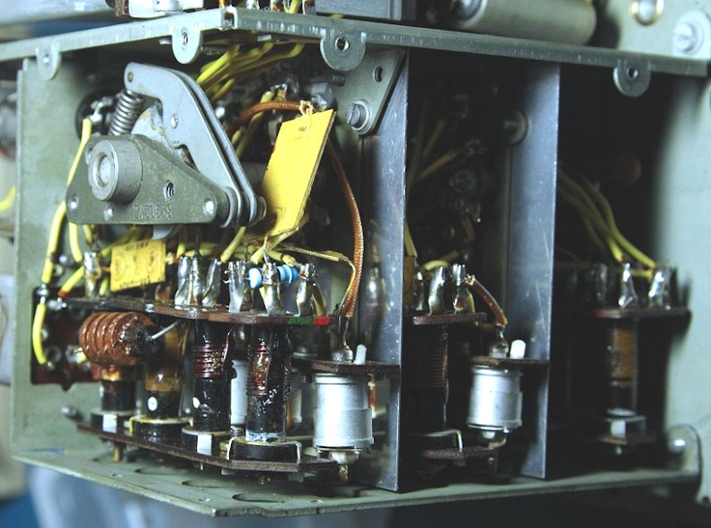
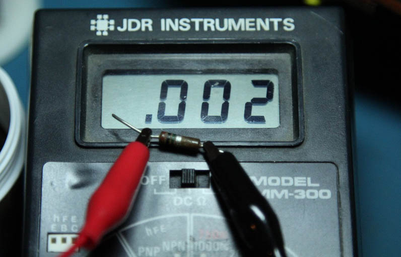
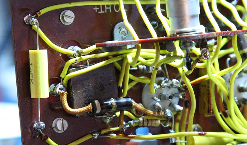
The other two resistors, the large blue ones, are 91 ohm resistors for the filaments of the two tubes/valves in this section. Both resistors tested high at around 110 ohms each, but I was not convinced that they actually needed to be replaced at the time. The worst resistor I encountered in this section was a 1M ohm that measured at 2K ohms! R40 in the audio section. I didn't believe it! I removed it from the circuit and tested it again, same reading. Then I tested my meter to make sure it was working correctly. All was well, aside from the resistor that is. The photo below is with the meter on the 20M ohm setting.
At the risk of sounding like I have little experience, I had never run into that before. I've found open resistors, I've found burned resistors of all values and sizes. I've even found improperly coded resistors. Heck, I even have a 2N2222 bipolar transistor that tests as a PNP junction! I thought I had seen it all! But I had never found a resistor that far off before without some external sign of damage. I assume it must have been mislabeled at the factory and never tested before it was installed. In that case, perhaps some of the issues with this receiver were present since it was manufactured. Anyway, moving on. Working on this section was a joy compared to working on the band switch assembly. I removed the screws from the bracket securing it to the phenolic board to make things a bit easier on myself. Some components are on the top side of the board (under the speaker housing when installed), others are on the bottom side of the board and others are on the mode switch. Namely, three resistors.
Some may wonder why I use such an eclectic array of parts. While I try to keep restorations tidy by using matching parts, I often find myself impatient and having to use what I have on hand. And other times, a certain part seems to fill a void better than others. Such as the case of the components under the speaker where I replaced carbon composite resistors with new carbon composite types rather than carbon film. I had some, they look nice, and so it was done.
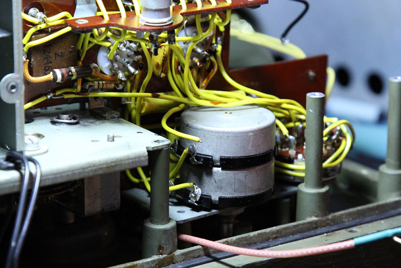
The large electrolytic on the top side of the board is a 500uf 6 volt rated non polar capacitor. I tested it out of curiosity and it showed a lot of leakage on my component tester. I'm never sure how trustworthy those measurements are, but the theme of this restoration seemed to have been to replace any capacitor that wasn't a mica or ceramic type, so out it went. I used a polarized 470uf electrolytic mounted on a turret board that I made to fit the original location.
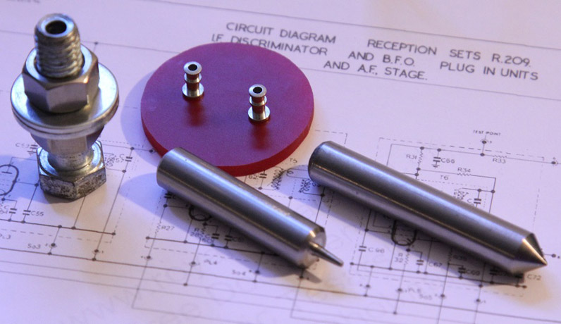
I made the turret setting tools on my lathe a few years ago and they have come in very handy. A lot of people prefer to restuff old cans and bathtub capacitors, but I consider using a custom turret board to be an attractive and period appropriate way of doing it. The photo below is how it looks from the bottom. The tall sides of the turrets protrude through the original holes in the board for the capacitor leads. This allows for an easy tie in of the appropriate leads and a clean finish to the electrical work on this section.
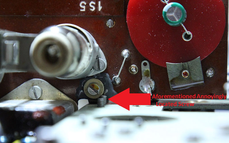
With the electrical work completed, I still had to deal with the broken phenolic board. This rather simple issue ended up taking up more of my time than all the electrical work on this section. I thought about many ways to fix the break. Using fiberglass board or aluminum to reinforce it around that area was the best option in my mind, but the close proximity of other components and one particularly annoyingly placed screw made that impractical. In the end, I settled on using JB Weld two part epoxy to both glue the board back together in that spot and reinforce the area. It's not ideal, but as of the writing of this article, it's still in one piece.
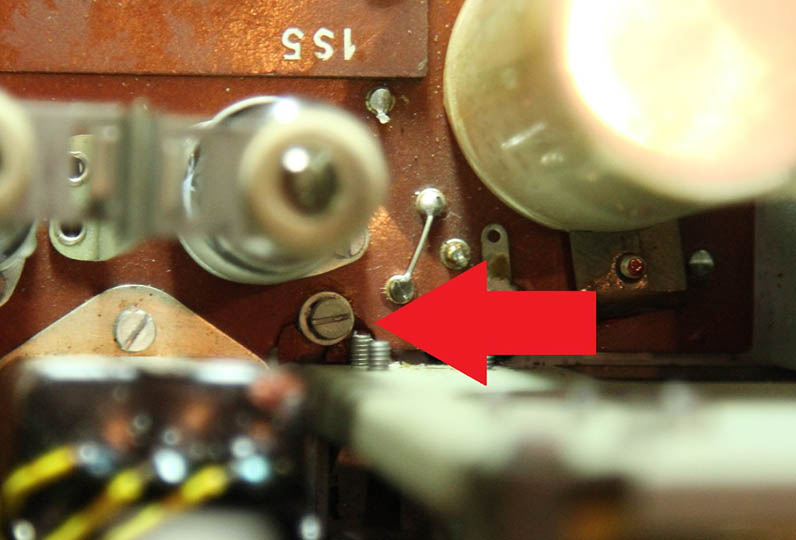
In the above photo you can see the pesky screw, epoxy repair job, and the round turret board that I previously mentioned with the replacement electrolytic capacitor mounted on it.
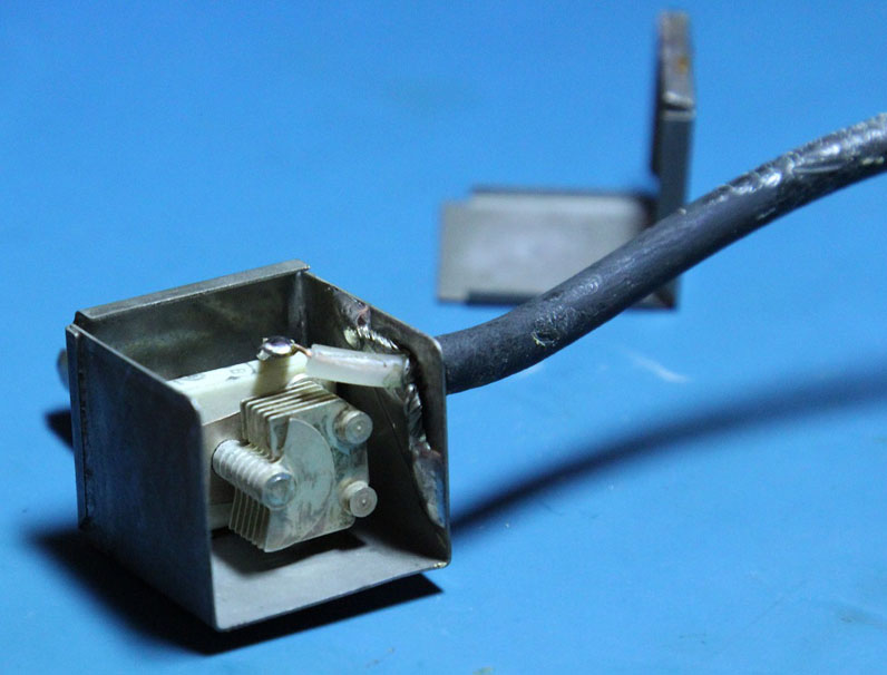
While the epoxy was drying, I figured I'd give the BFO control a little attention. Nestled between the speaker compartment and tuning drive assembly is a small metal box containing a 25pF trimmer capacitor, this is the BFO control, as seen above. To remove it from the front panel, the disassembly process is the same as for the other controls aside from the rubber seal being contained in a nut that screws onto the trimmer shaft housing. Once removed, I de-soldered the rear cap of the metal case to open it up. I took this opportunity to clean it as well as replace the original coax which was rather beat up and very stiff with a short length of RG174. I then resoldered the metal case cap and reinstalled the trimmer. Below is what the trimmer looks like.
After a few days of letting the epoxy cure, I set about reinstalling the terminal board assembly. As I expected, I found that the epoxy needed to be sanded a bit to make it fit correctly. The pesky screw left just enough room for the board to fit between it and the bracket. The epoxy I had applied made it a bit too thick. After some sanding and a decision to drill out the tapped bracket, I was able to get the board to fit correctly. I drilled out the bracket and replaced the short 6BA screw with a longer one along with a nut. This made installing the board easier as the alignment was not as crucial. Once I had reinstalled the board assembly, I noticed a broken wire that had occurred at some point. A bit of tracing later and I found that it came from the center terminal of RV1B, the front section of the gain control potentiometer. Below you can see the broken wire floating near the potentiometer terminals as well as the new RG174 coax for the BFO control.
Below are the components replaced in this section.
Below are two photos of the completed section, one from the top and one from the bottom. The two black wires visible in both pictures are the headphone jack leads that I did not reattach yet.
Removing and reinstalling this section of the radio requires the use of very long and thin screw drivers. I happen to have a set that works well. All the screws in this radio are slotted and the slots are unusually narrow for the size of screw. It seems a sharp chisel would do a better job than most screw drivers! Due to this fact, care must be taken not to mangle the screw slots when removing and reinstalling them, lest they become impossible to remove.
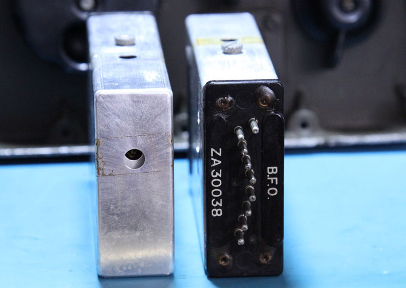
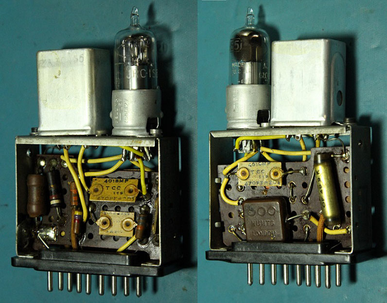
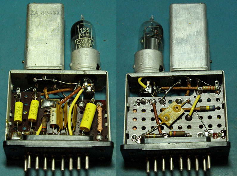
With the finished section and power supply reinstalled, I plugged in the various other modules and tested the receiver. I was still having the issue of having the neon regulator bulb go out often. Replacing the clip leads I had been using to connect the power switch to the power supply section fixed this somewhat, but it was still occurring now and then. Various other issues were still present when operating the radio. The BFO would cut out sometimes and the overall gain of the radio varied. Sometimes the neon regulator going out would affect this. When the BFO was operating, often times the maximum gain in the speaker was somewhere around the middle of the gain control range rather than at the top end. This was not always the case though. The BFO was also unstable while operating, although not as prevalent as before. Wiggling the module would make a difference leading me to believe that the terminals of the plug in modules needed some attention. The BFO also lost the raspy CW note that it had previously, so my work somewhere paid off. Perhaps the new electrolytic capacitor improved any hum present on the filament line. With the main chassis components of the radio done, the plug in modules were all that were left. I decided to start with the BFO module. In the photo below, you can see how each module looks from the top and bottom. The bottoms are labeled according to what type they are and each of the three types have a different pin arrangement to make them impossible to mix up when installing them. The tops and rear sides have holes in the aluminum cases to adjust the coils within them. The BFO adjust from the top only, but the side hole is still present.
The thumb screw on the side of the aluminum case is removed to allow the case to slide off of the frame exposing the circuitry inside. The inside of the cases each have a rubber block that hold their respective tube/valve down into their socket. Below you can see the BFO frame from both sides.
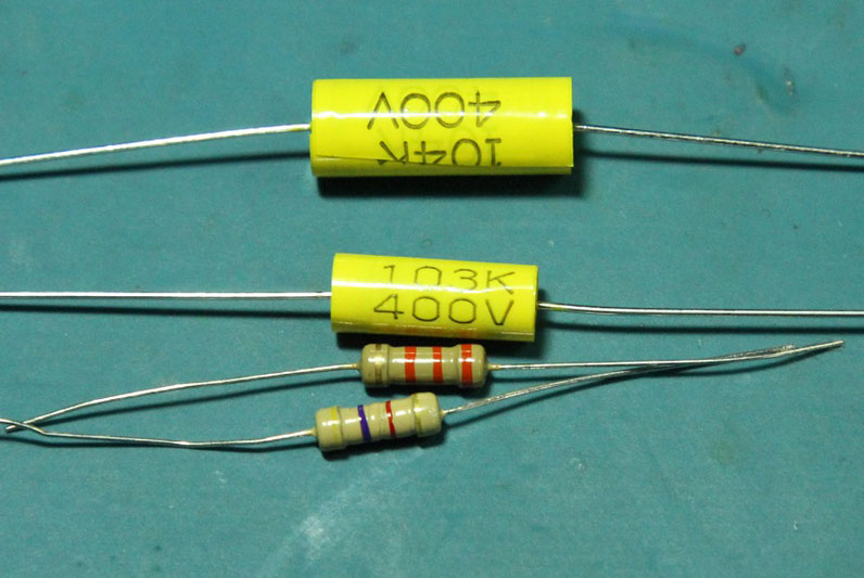
I went through the BFO and tested the resistors finding two that needed replacement. The filament resistor was also high like the others I had tested, around 114 ohms. I chose to leave it for now as well. There were also two capacitors to be replaced. I also noticed that the tube/valve in it is an RCA tube/valve. Not all that unusual, just interesting to see American made tubes/valves in a Belgian radio receiver. Below are the new components prior to installation.
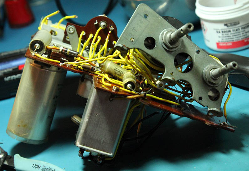
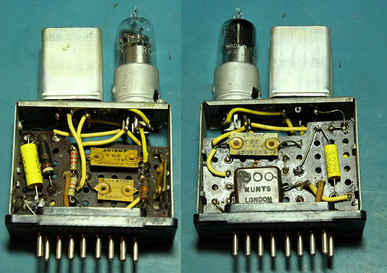
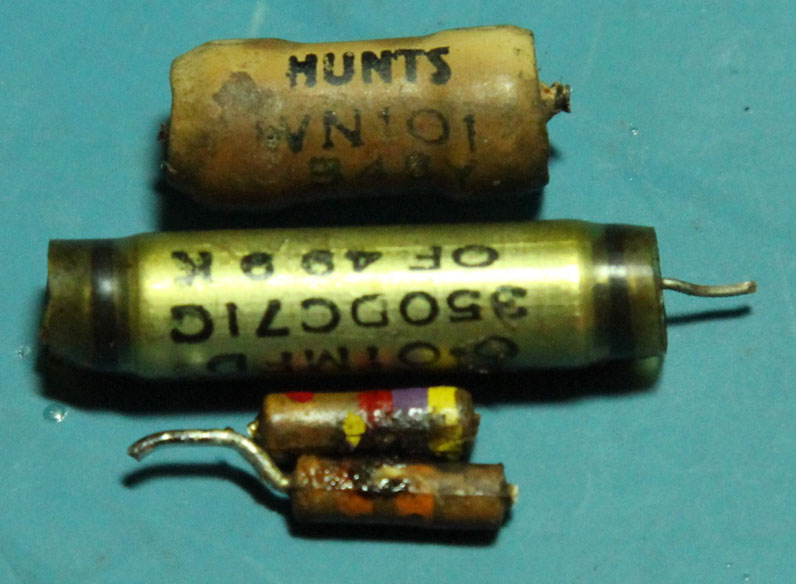
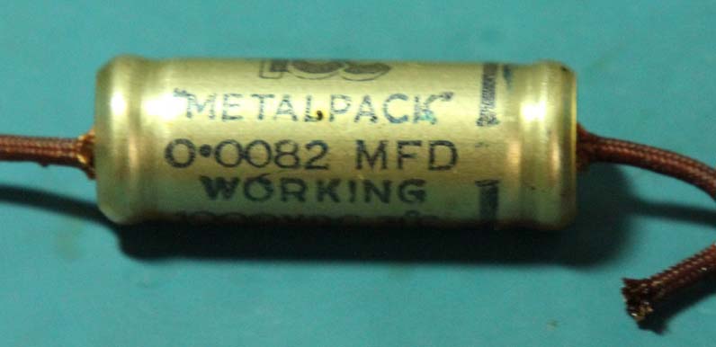
Below the BFO module is pictured from both sides after installing the new components as well as the components replaced in this section including the 0.1uF Hunts brand capacitor that looks very much like a resistor.
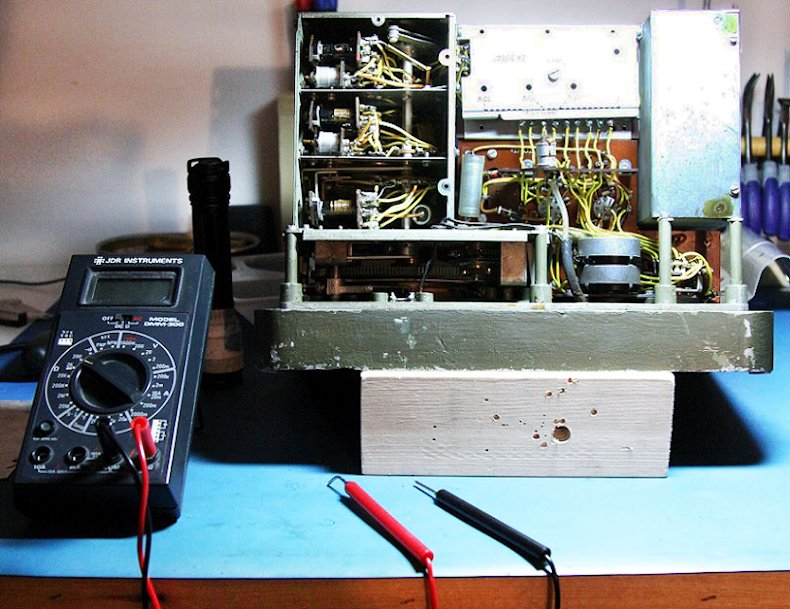
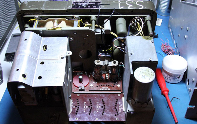
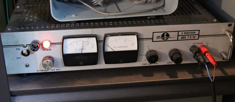
Once I was finished with the BFO, I installed all the modules and tested the receiver again. I generally run this receiver with an old adjustable DC power supply although it can be run on batteries as well. It draws around two amps. The power supply I use is old and heavier than the radio, but it puts out very smooth DC with no perceivable ripple. It can be seen below. I did not notice any real improvement in functionality when testing the receiver again, but the BFO still worked as did the rest of the radio, so satisfied, I moved on to the detector section.
The detector section also known as the discriminator section due to the unusual FM capability of this receiver, is the same sized module as the BFO. Removing the case shows the same basic design layout as the other sections as seen below, again, from both sides.
In the same fashion, I went through and tested the resistors and gathered up the necessary capacitors and replacement resistors for the ones that tested out of spec. In reality, they are generally all out of spec, but I consider anything greater then 10% out of spec goes. Speaking or resistors, the filament resistor in this section is a precision type. Still not perfect, but it measured 94 ohms instead of 91. That's definitely close enough. Below are the replacement components before being installed in this section.
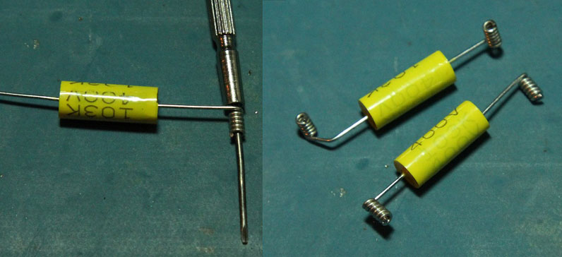
To go a little more into detail about how I generally replace components, I took a few extra pictures of the work in this section to explain. In a lot of cases, older electronics like this can have some terminals that are fragile. Either because they were never really designed to be reworked or because they have fallen victim to age. Whatever the case, I like to take a minimally invasive approach most of the time. I often cut the leads close to the component to be replaced then I coil the leads of the replacement component around a mandrel of some sort. In my case, a jeweler's screw driver. These small coiled leads can then be dropped over the remaining leads from the original components and soldered in place.
Before placing the new components in position, I always apply some flux to the original leads. Sometimes they even need to be scraped or sanded especially if there is lacquer on them. With old, potentially corroded leads like these, proper preparation ensures a good electrical contact.
I cannot take credit for this method, I picked it up from many other people doing similar restorations. Some make simple single turn loops, but I like the look of small coils. I use this same method for disconnecting and reconnecting wires and component leads. Sometimes a resistor or capacitor wired across a coil must be checked or a wire disconnected temporarily. In these cases I snip the lead somewhere near the middle, then proceed with the test and if the lead is to be reconnected, I make a small coil out of buss wire and slip it over the lead then solder it. I find this much easier than desoldering a terminal, especially if the leads is all wrapped around it. Anyway, the completed detector/discriminator section can be seen below.
Below are the components I replaced from this section. The red dot on the resistor is nail polish. I use it to mark bad resistors as I go through and test them. It makes it easy to know which ones are bad when I go back in to replace them, especially in crowded locations with multiples of the same value. The capacitors in the middle are the .01uF capacitors used in these sets. In my opinion, they are the best looking vintage capacitors I have seen with their nice little extruded aluminum cases.
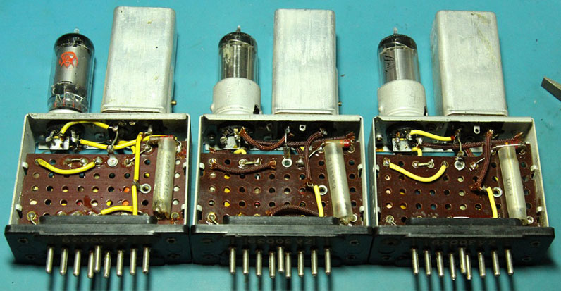
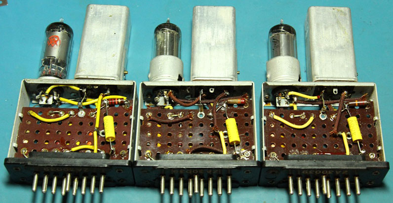
Another note regarding capacitors. In most of my restorations, I use and oscilloscope to find the outside foil lead of new capacitors and install them with the outside foil to the lower impedance connection. Another trick I picked up over the years. In that orientation, the outside foil of the capacitor acts as shielding to keep hum off of the higher impedance connection. The high impedance lead should also be as short as possible in that case. I didn't worry about all that in this receiver as everything is quite well shielded and there are no AC filament lines to worry about. With the detector section now done, I reinstalled all the modules and tested the receiver again. As before, I did not notice any appreciable difference in the receiver performance, but it still worked, so I was happy. With only the IF modules left to inspect, I continued on my way. All three modules are the same and can be interchanged, a design factor of the radio meant to make easy work of servicing. I pulled the three modules and removed them from their cases. As you can see below, each one is a little different from the next.
The far left module has a tube socket without a shield ring. It looks to be an original socket. Perhaps it was a change along the line as they were manufactured. It also has a regular carbon type filament resistor like the middle module, both of which tested high like the others. The far right module has a precision type resistor that tested right on 91 ohms. Aside from the filament resistors, I only found two resistors to be replaced in all three modules. There were also nine capacitors. Two 0.01uF and one 0.1uF per module. Below are the new parts.
Changing the components went smoothly. I used a carbon composition 22K resistor rather than a carbon film as I had just used my last carbon film in the detector section. Below are the modules after replacing components as well as the components replaced.
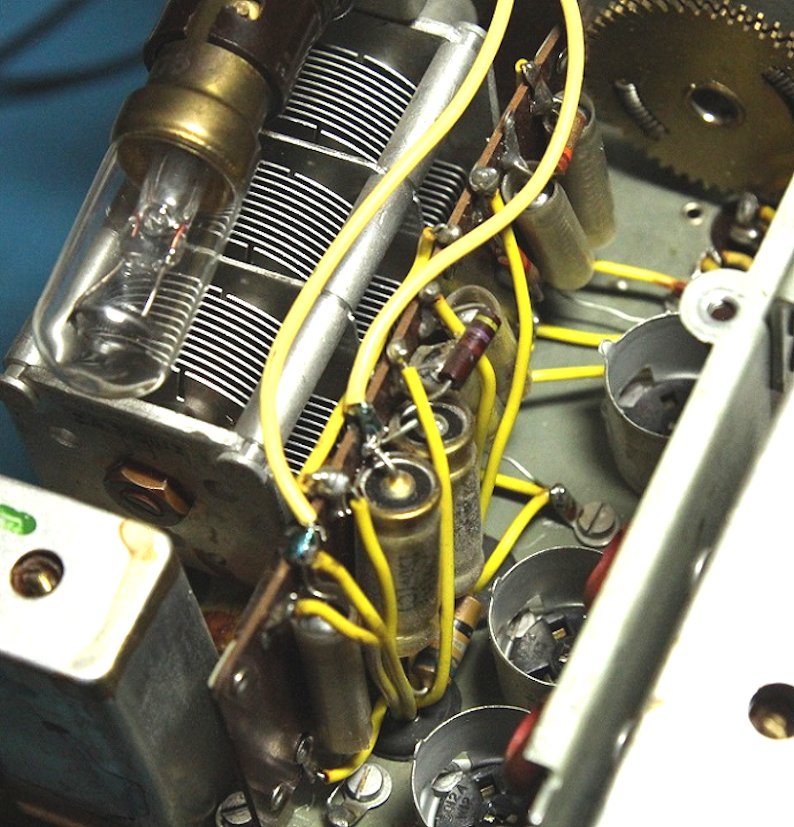
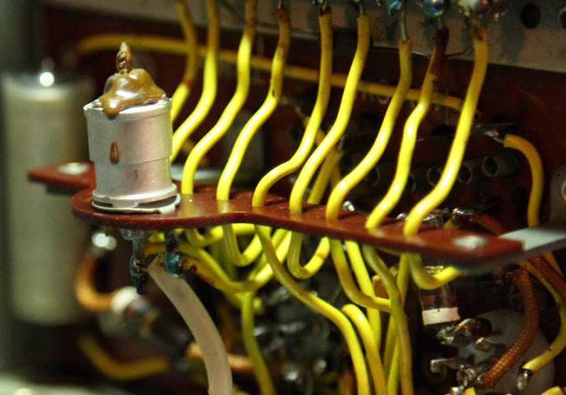
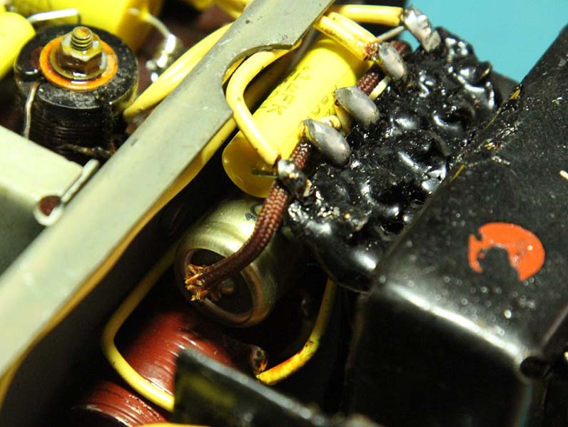
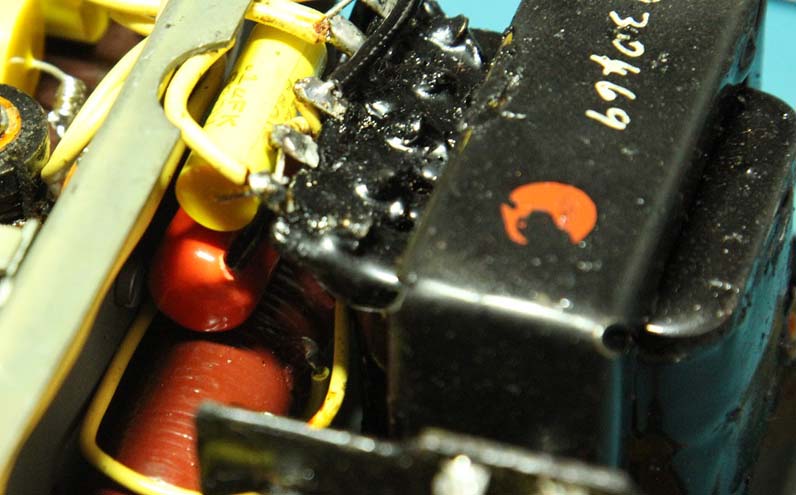
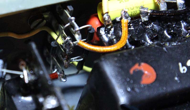
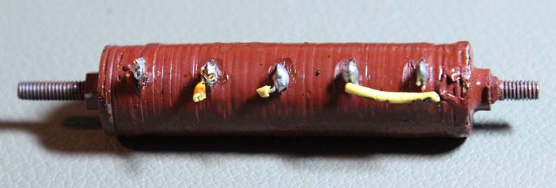
With the IF modules recapped, I reinstalled them and tested the radio again. It was about the same as before operation wise. The neon regulator was still going out now and then, but not as often and when it did, I could get it to come back on with a little fiddling with the controls. At this point, I thought about replacing the out of spec resistors for the filaments as well as the buffer capacitor in the power supply, all of which would have to be ordered first. Clearly I was not quite done with the electrical side of this radio restoration. The buffer capacitor used in the power supply is a 1000v .0082uF. I did not have any of that value on hand and in a rush to see if replacing it would help at all with the HT voltage, I choose a 1600v .01uF orange drop capacitor. Removing the old capacitor and testing it showed a similar value when compared to the replacement, so I figured it would work fine. The photos below show the capacitor before and after replacement as well as the old capacitor once removed. The red colored tube below the buffer is the selenium rectifier which would be the next part to be replaced. : With the buffer capacitor replaced there was no perceivable difference in performance. The HT voltage was about the same as before and the neon regulator bulb continued to go out. Some suggestions from Keith in our email correspondence lead to me measuring the HT current draw which lead to no real conclusions. It did not seem that any particular section was drawing excess current and pulling down the HT voltage. The next rational step was to replace the selenium rectifier. Even if it had aged well, a modern silicon diode bridge would have less voltage drop The selenium rectifier is tough to get to being under the buffer capacitor and between the transformer and metal case of the power supply. I cut the leads running to it then unscrewed the clamps securing it in place. Once the rectifier was pulled out, I built a bridge on a four lug terminal strip using four 1N4007 diodes. I then installed the bridge next to the transformer and wired it up. It can just be made out in the photo below. I meant to take a picture before installing it, but I forgot. Below is a photo of the old selenium rectifier.
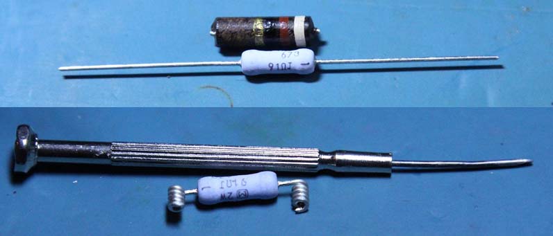
With the new rectifier bridge installed, the HT voltage of the radio was around ten volts higher than before. 115v on average. The neon regulator bulb would now stay lit even with the input to the radio being under six volts. Throughout this restoration, the regulator bulb going out was always the most frustrating for some reason. I was glad to have that problem fixed. The rest of the radio's performance seemed about the same as before. After several days of waiting, my new filament resistors arrived in the mail to replace the ones that had gone out of spec. The replacements are Panasonic 91 ohm, 2W, 5% metal oxide resistors. Below is a photo of one of the replacements compared with an old one and ready for installation followed, by a few photos of replaced resistors in their respective circuits.
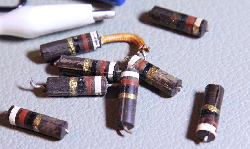
In total, I replaced eight of ten resistors in the radio starting with one of the IF sections. After this first resistor, there was an appreciable difference in performance. The radio definitely had more sensitivity than it did prior. I then did the same to the next IF and BFO sections, skipping the detector and third IF section as they both had precision resistors that had not drifted much in value over the years. Next I moved onto the audio sections and RF and local oscillator sections. An increase in audio gain was very apparent once the resistors in those sections had been changed. In most cases, the filament resistors had drifted up in value by about 20 ohms although the best one I replaced was only about five ohms high. I probably could have left that one alone, but I figured I may as well go all the way in regards to changing them. Below is a photo of the old resistors.
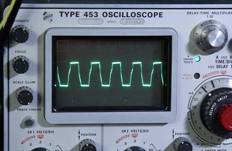
As previously in this restoration, the use of long, thin tools was necessary to get at some of the resistors. I had to remove the plastic handles of a pair of wire cutters in order to cut the bottom leads of the resistors for the RF sections as I did not want to remove the tuning capacitor to get at them. In the end, they turned out fine. I did learn that I could do with a soldering iron with a narrower heating element though. With all suspect electronic components replaced and the radio performing well. I checked the performance of the power supply to get an idea as to the condition and performance of the vibrator. The previous owner informed me when I bought the receiver that he had had to open up the vibrator and clean the contacts in order to get it to function. That implied to me that it may have been nearing the end of its useful lifespan. I hooked the output of the vibrator up to my oscilloscope to check the waveform. It was steady in amplitude and did not jitter on the screen much. I also hooked it up to my frequency counter and it gave a steady reading of 100hz. Right around where it was supposed to be. I also checked the waveform out of the power transformer and compared it to diagrams of waveforms in various states of closure to check the match of the buffer capacitor. The waveform appears to be that of a vibrator timed for under closure. Over closure produces high voltage transients that result in reduced life of the vibrator and potentially other components, so under closure is preferred. Below is a photo of the HV waveform out of the transformer secondary.
After the inspection of the power supply and having used the receiver a bit after changing the filament resistors, noting the improvements in performance, I was satisfied that the electrical restoration of this radio was complete. All that was needed now was a thorough cleaning of the switches and module pins, checking the lubrication, and performing an RF an IF alignment. More to come, watch this space ...... Eric Tesarski |