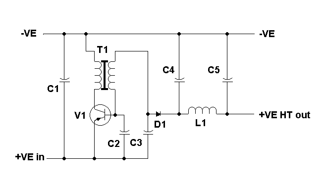
Simple Inverter brought to us by Jan Terranea
This version is mostly based on
publications in the Dutch "Surplus Radio Society" in 1995 and later.
This is a somewhat universal schematic I use to build small HT-converters for
portable tube-based (ex army) radio-sets. As far as I know this is an old design.
The value of the components will be a little experimental.
T1 = pot core trafo with air-gap
0,2 to 0,6 mm. Also depending on the AL factor.
I made the ht-coil first, then the LT-coil around it, so that adjusting the
ratio is easy to do afterwards.
The pot core-size depends on the size of the wire and the output power needed.
In my BC611 I used a 18*11 mm pot core, which delivers I think max.3 watts HT.
The primary is 12 windings 0,6 mm, secondary 200 windings 0,2 mm generates about
100 volts out of 6 volts dc.
36*22 mm delivers up to about 15 watts. etc.
Pot cores are difficult to get in regular shops, but I do visit several radio/electronic
flea markets
where I look for them, bare or wound, or on commercial PCBs.
Commercial prefabs might be glued together, so these pot cores must be cooked
in water like an egg to weaken the glue.
The coil-formers are not very rigid and they are even harder to obtain.
A friend could supply me through Philips with a minimum lot of 100 pieces pot
core complete 36*22 at a price of 5 euro a piece,
but I own a hobby and a small radio-shack, not a professional workshop with
a lot of machinery and customers.
I have built a test-converter so
that I can easily check the results of a pot core trafo, as well as the value
for capacitors and choke.
To identify the pot core leads I make use of 4 colours of wire-isolating: black
= negative LT, yellow = emitter, green = base, red = ht-rectifier.
V1 = PNP transistor such as: BD808/BD810/BD912
or larger BD246/TIP34.
a small heat sink is sufficient as little heat is generated, the converter-efficiency
is about 80 %.
C1 = 1.000 uF to 2.200 uF for improving/lowering the internal resistance of
the battery. It could be omitted to gain some space.
C2 = 0,1 to 0,22 uF 250 or 400 WV, depending on the HT-voltage
C3 = 0,0022 to 0,0047 uF Ceramic, 400 WV.
C4 = about 10 uF electrolytic about twice the HT-voltage.
C5 = about the same as C4.
D1 = silicon diode. For HT up to 100 volts I use BYV27-200; for higher HT I
use BY228. Anyway a fast switching-diode.
L1 = filter-choke about 2-10 mH.
If the converter does not start,
but there is a LT-current flowing, then the first remedy is to change the connection
of transformer primary windings.
