The
Wireless-Set-No19 Group
Royal Signals
www.royalsignals.org.uk
R210
Restoration
By Keith Watt RGN (Rtd.)
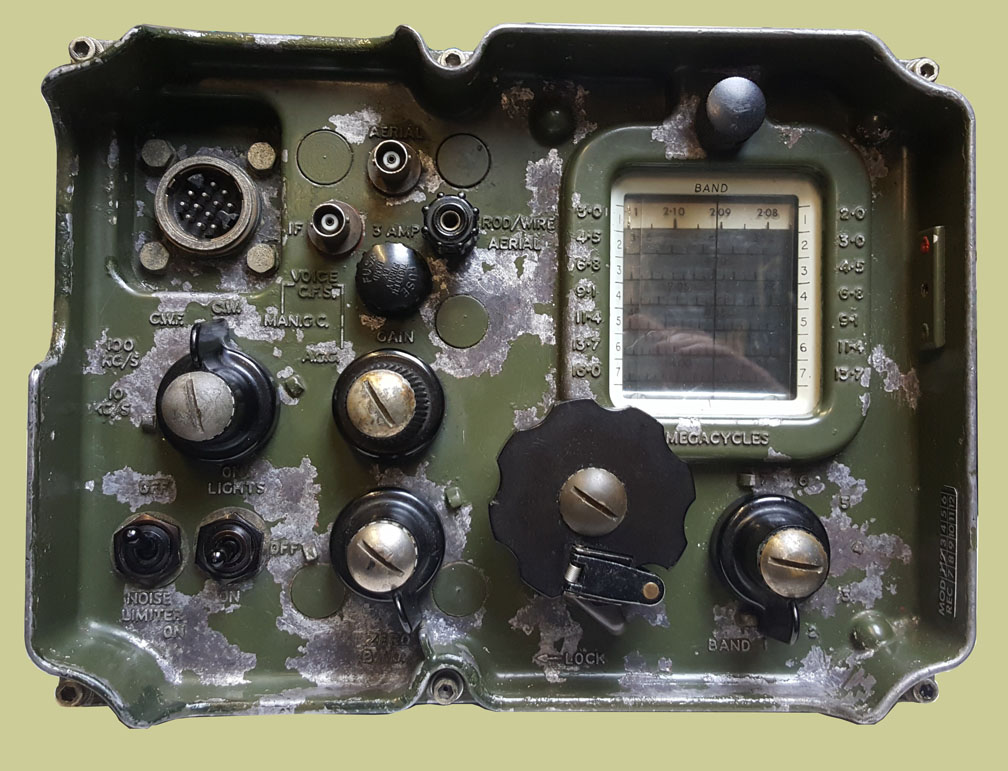
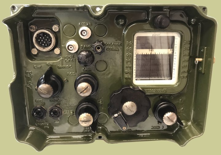
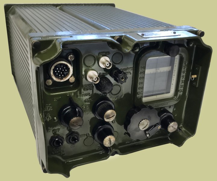
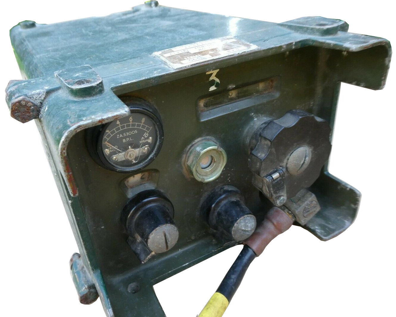
Front view before start of restoration.
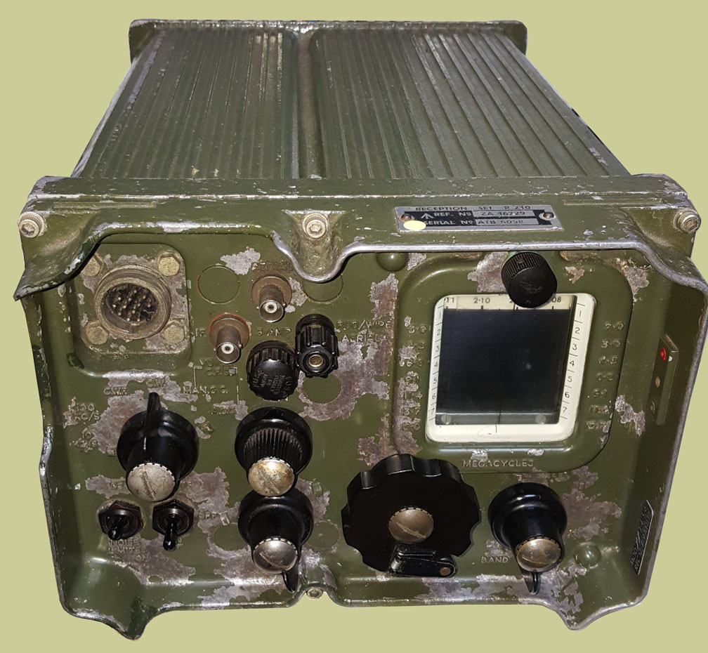
Front and top view before start of restoration.
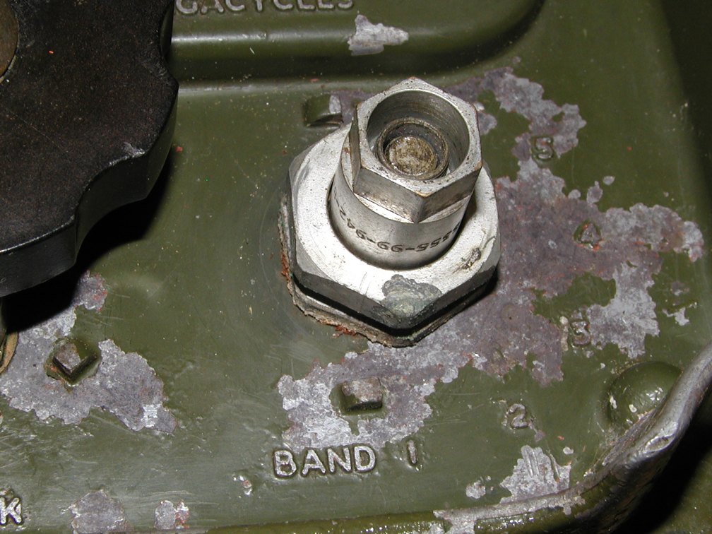
Close up of the collet assembly behind the knobs.
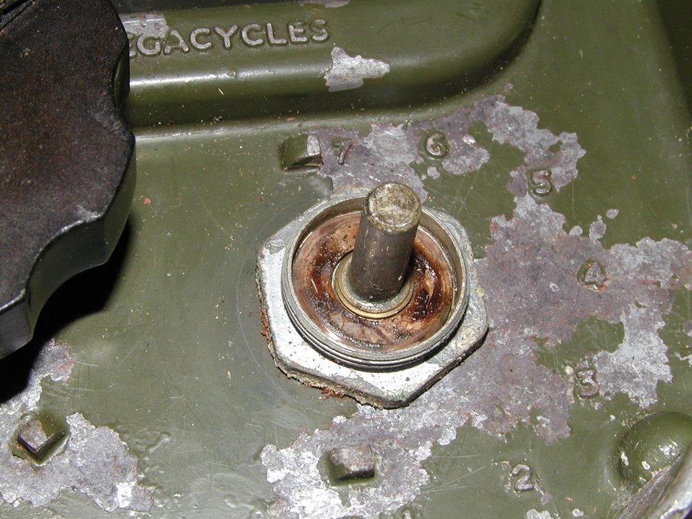
Close up of the collet
assembly behind the knobs.
(The brown residue is grease.)
One of the two BNC connectors,
Aerial and I/F Output.
This is before cleaning.
One of the two BNC connectors,
Aerial and I/F Output.
This is after cleaning.
Cleaning having
been done using a common sink cleaner called Cif and an old tooth brush.
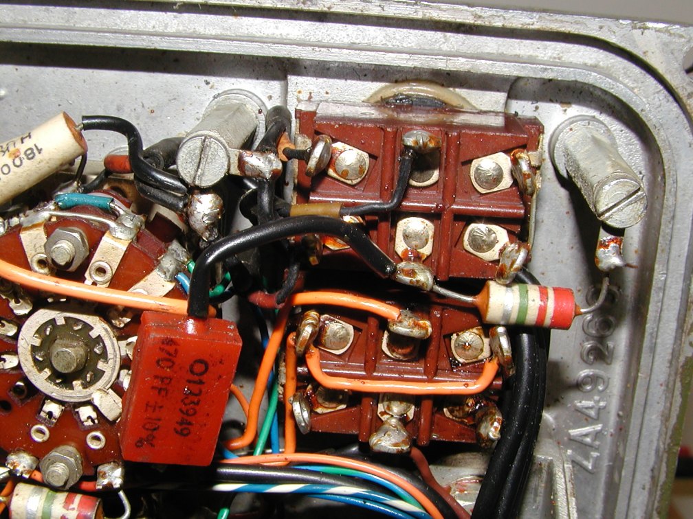
Close up photos were taken of the backs of all the controls that were going
to be unbolted
from the front panel. A wise move just in case anything becomes disconnected
you can easily
see where it came from. A photo of the wiring also helps when putting things
back
together, so you know where the wiring sits behind the panel.
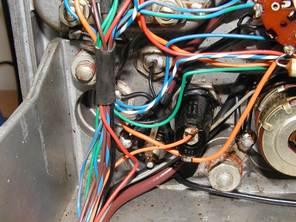
Behind the front panel
- main connector.
Some of the installation sleeves need to be slid back over the soldered joints.
Behind the front panel - Mode Switch.
Behind the front panel - Power Switches.
Behind the front panel
- RF connectors and Fuse Holder.
Note the large nuts on the front panel studs, these nuts/studs are
what
hold the front panel on to the chassis. A small socket set is a must to get
these undone.
There are five such studs in all, each stud also has an O ring seal between
its head
on the front panel side and the front panel itself.
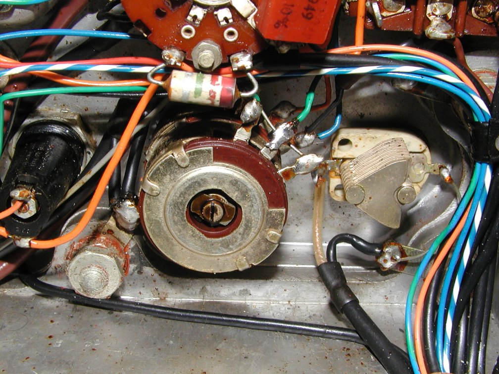
Behind the front panel
- Volume control and BFO control.
And there's another one of those five large front panel retaining studs!
All name plates have
been removed by popping out the rivets from behind using a small punch.
The rivets come out quite easily and are used to reattach the ID and Mod Record
plates after painting.
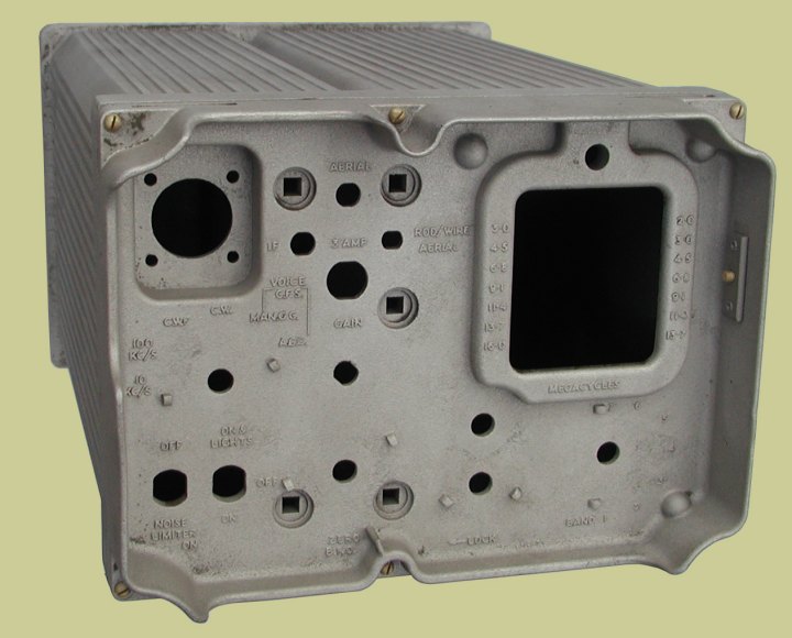
This is how the case
now looks after having been cleaned of all its old paint.
You can clearly see the five round head/square shaft front panel stud holes.
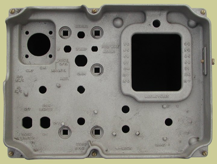
The case screws are just sacrificial 4 BA long bolts used to keep the case
closed while being sand blasted.
In hindsight I should have put a piece of thin plywood between the front panel
and the outer
case so that the sand blasting medium didn't fill the case. As a result I
had quarter of a case full of
grit and grease that I had to wash out with solvent! Be warned..!
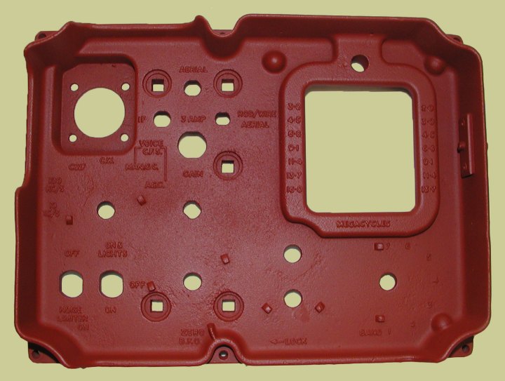
The front panel now has
a coat of red oxide undercoat paint,
ready for its final colour of BS381c, shade 298, Olive Drab, gloss finish.
Colour information courtesy of Andy Jackson.
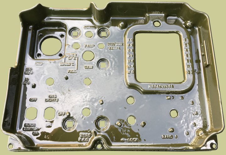
The front panel is now
finished, its has has received its final coat of paint.
Once the paint has hardened, it will be reassembled and mated back up with
the chassis.
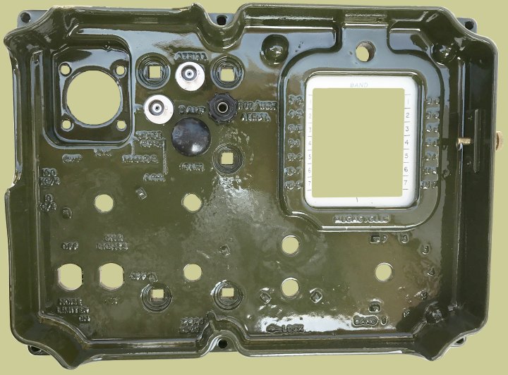
The BNC sockets for IF output and Aerial input, together with
the terminal for use with rod or wire
aerials, the fuse holder, and the tuning scale window with its escutcheon
are now in place.
A new brass 2 BA knurled head bolt with D ring to prevent it being fully unscrewed,
has been
inserted in to the ground connection on the right side of the front panel.
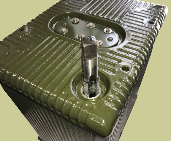
When trying to insert
the desiccator window and the vent plug, the threads were very tight. All
the holes had been
previously protected from ingress of sand blasting medium and paint, but dirt
had still found its way into the threads
making it difficult to re-fit the desiccator and vent plug.
A posting to the Wireless-Set-No19
Group revealed that the threads are 3/4" x 20 TPI UNS.
A tap and a die were ordered from Tracy
Tools and the threads cleaned out by running a second tap
through the desiccator and vent plug holes. Now the desiccator and vent plug
screw in with ease.
All the knob collet assemblies have been cleaned and lubricated
with silicone grease.
The paint has finally hardened and the assembly of the front panel started.
Name plates and MOD plates have been put back in place using the original
rivets.
Seals on the main connector put back in place around the bolts.
The main case seal has been inspected and looks perfectly OK to reuse.
It will get a very light coating of silicone grease before being put in to
the
slot around the rim of the front panel.
The only real thing left to do is clean the knobs, using
an old toothbrush and soapy water.
I might try the Cif treatment on the collet screw
heads to see if they will clean up.
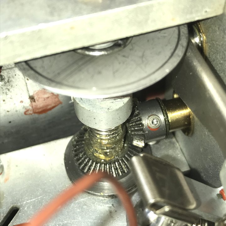
Notes when reassembling;
If you find you have
backlash on the tuning knob, you can move the tuning knob slightly without
the dial actually moving.
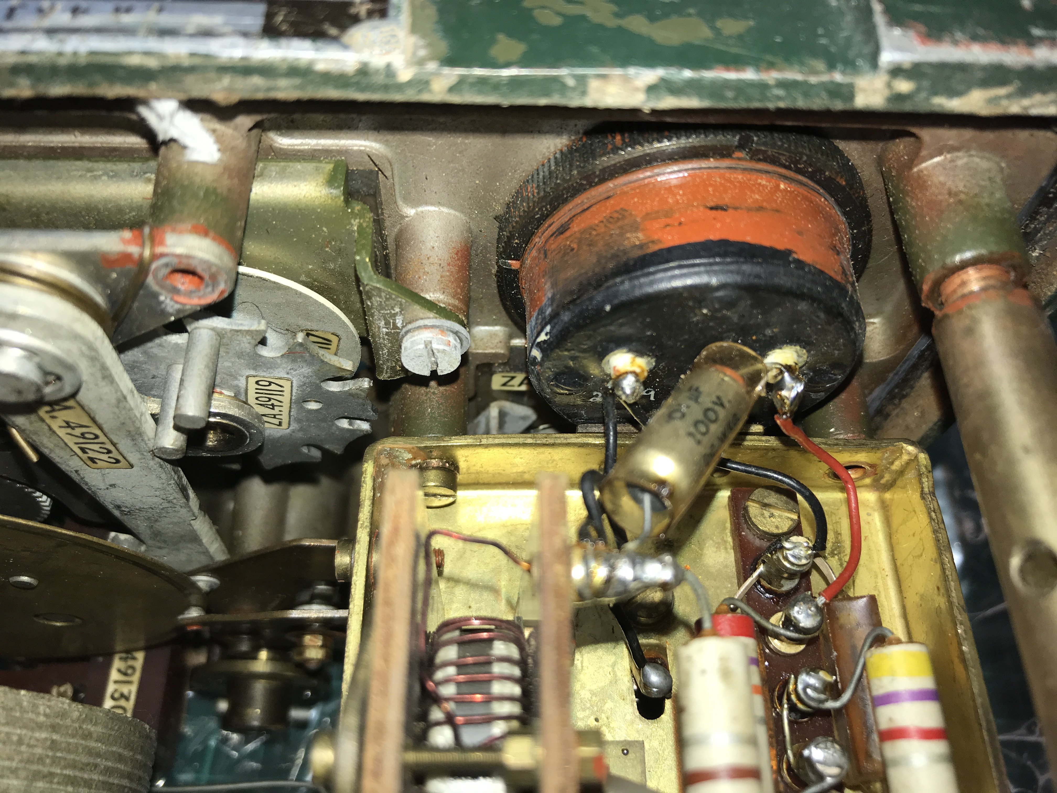
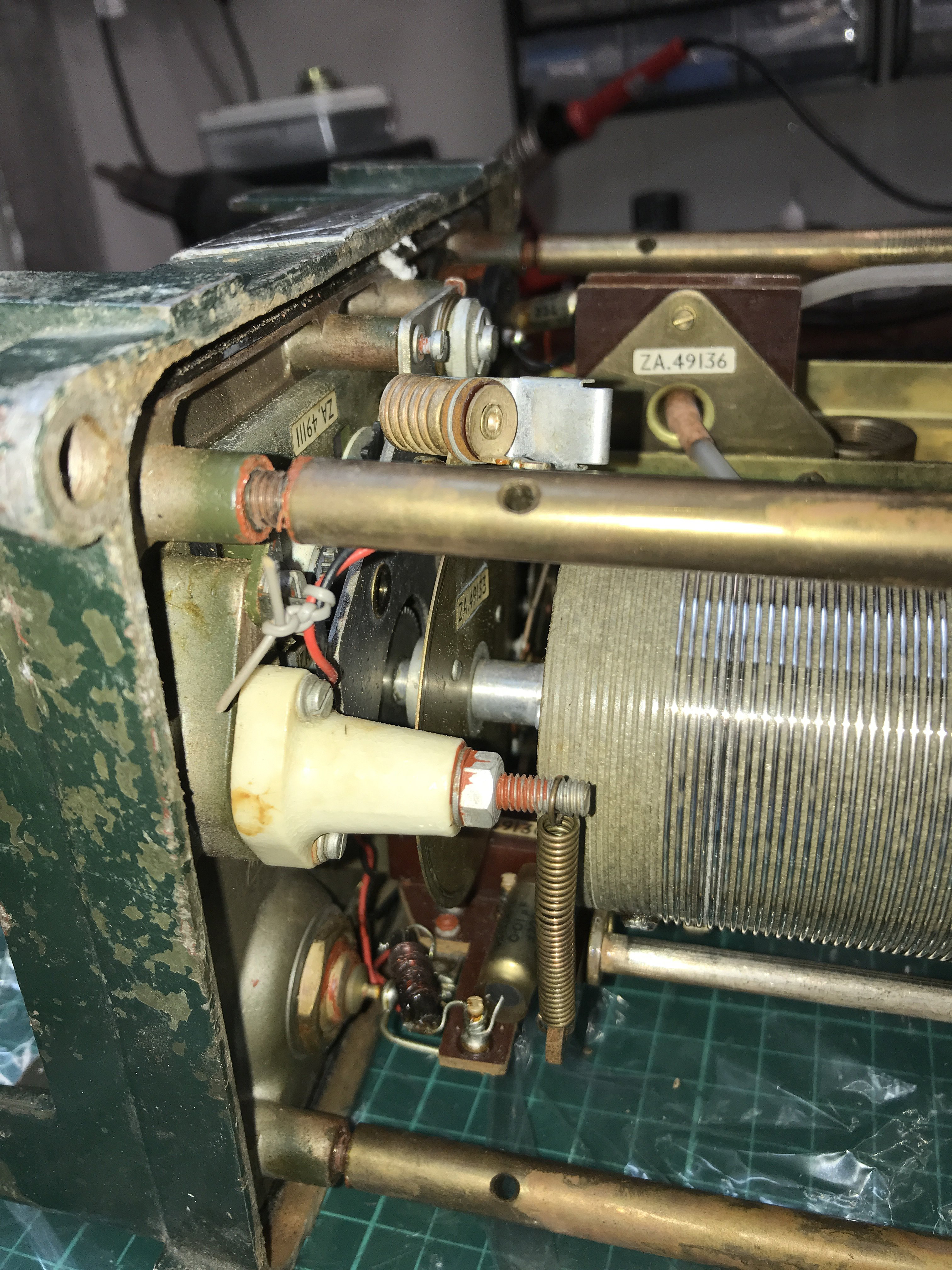
There is an easy adjustment to take up the slack in the gears between the
knob and the tuning dial drive gears.
The photo above shows the bevel gear, you can see one of two Allen grub screws,
loosen both grub screws and carefully and gently,
push the gear wheel away from the front panel, it will make the gear wheels
mesh a little more and take up the slack in the drive.
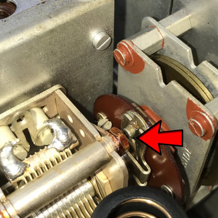
When I refitted the film
scale unit I found it had horrendous backlash in the tuning.
I could turn the tuning dial quite a way before the receiver actually moved
frequency.
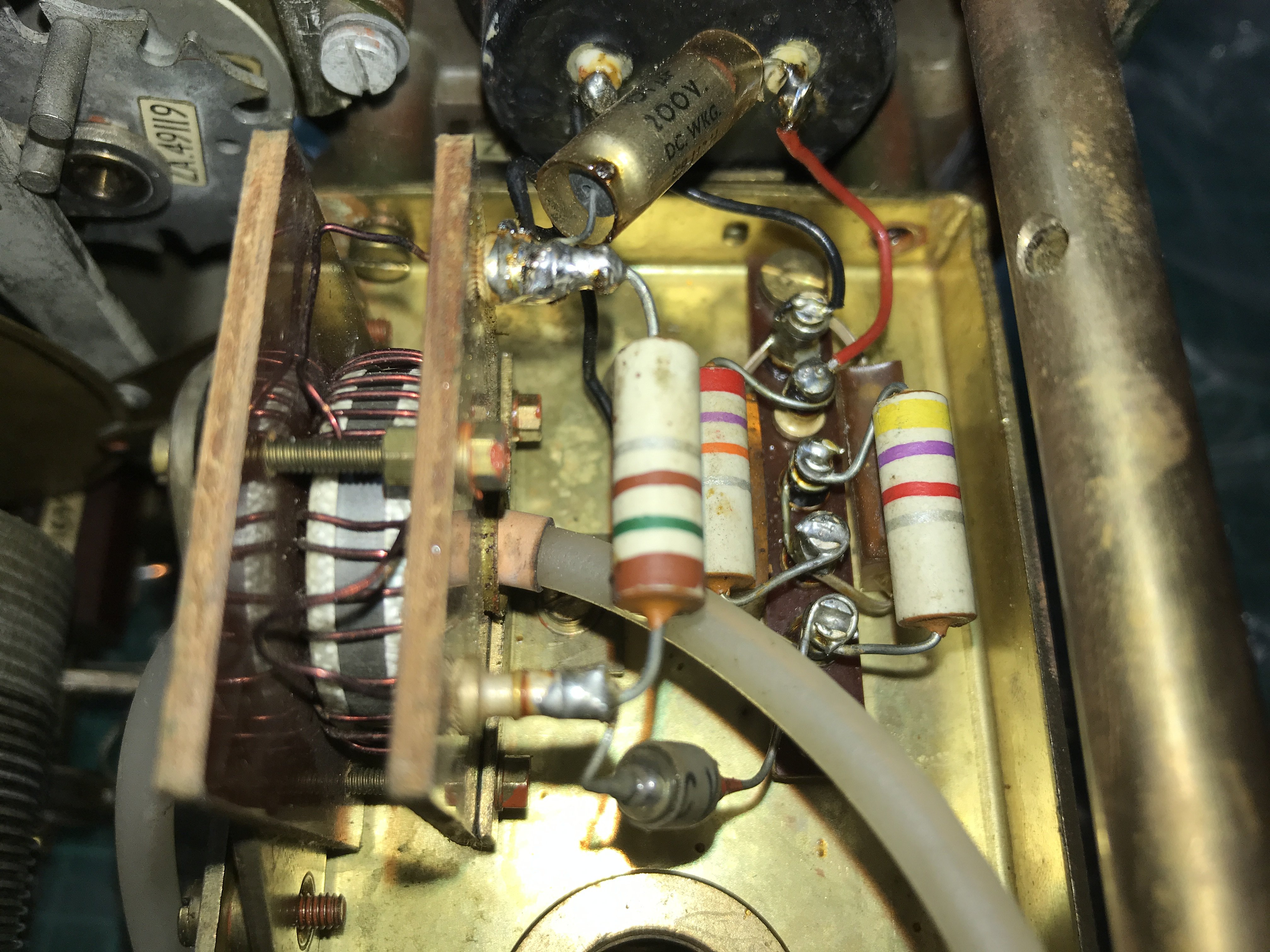
Upon looking at the R210 EMER E284, Archive document number 1194,
it mentions checking the springs on the flexible coupling.
In the above photo the spring in question is highlighted with an arrow.
The spring was actually sitting the wrong side of the pin that it rests upon,
repositioning the spring cured the backlash problem.
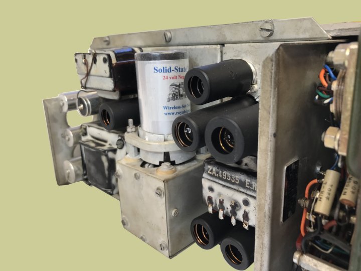
The original vibrator is still in working order, but I thought
it best to fit a new
solid-state vibrator from the ones that we sell. As can be seen, our octal
base
24 volt synchronous solid-state vibrators are a direct plug in replacement
for the
old original mechanical vibrator. The vibrator clamping assembly holds the
new
solid-state vibrator perfectly.
The chassis has been fitted into the case.
The locating pins/plate on the back of the case has now been tightened up
after the chassis was inserted.
The case is now fully restored and a new desiccator fitted.
I thought it would be a nice to be able to fit seals back on to the 2BA Allen
head bolts
just as the R210 would originally have had. These were obtained on eBay.
With the help if Chris Suslowicz and Chris Jones, I hope the
next project will be a home grown
"A" box to connect the R210 to a 24 volt supply and audio out to
headphones and or speaker.
The R210 has a new lease of life and I hope for many more years of enjoyable use from it.
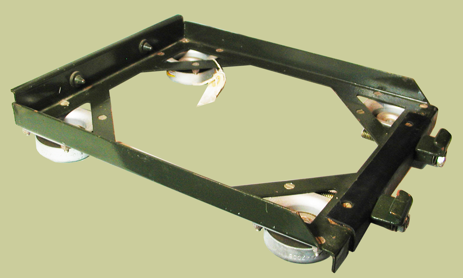
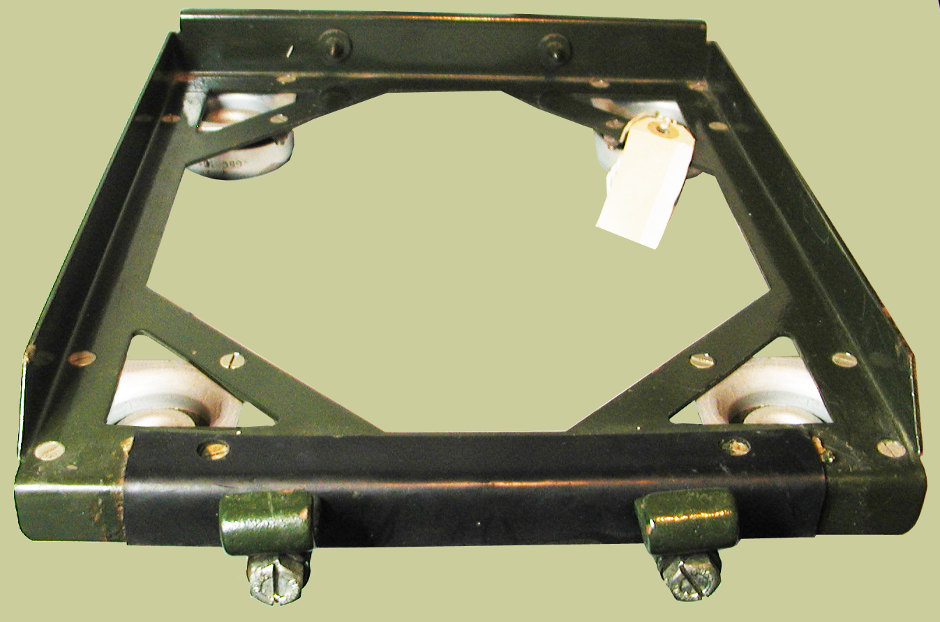
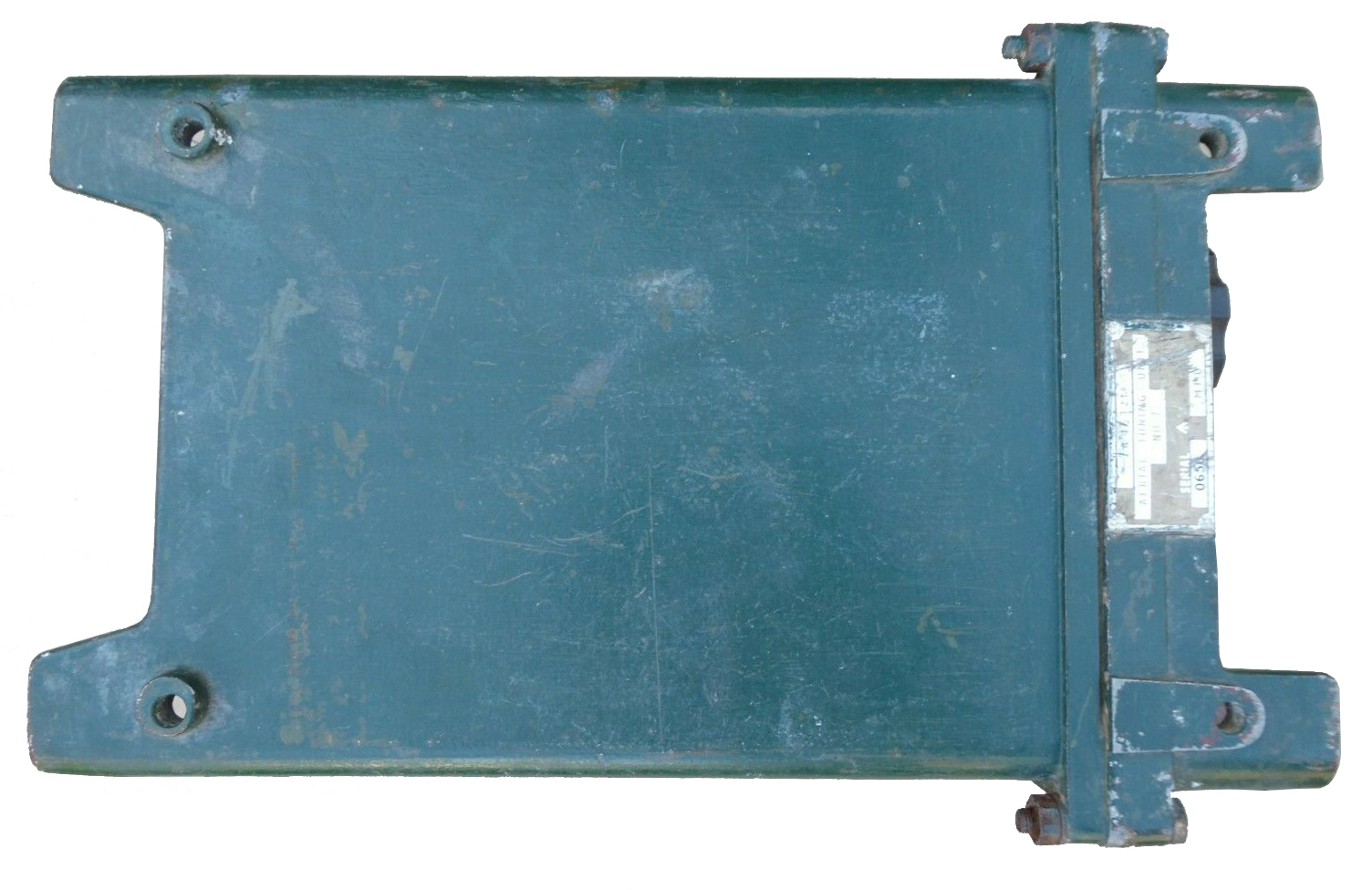
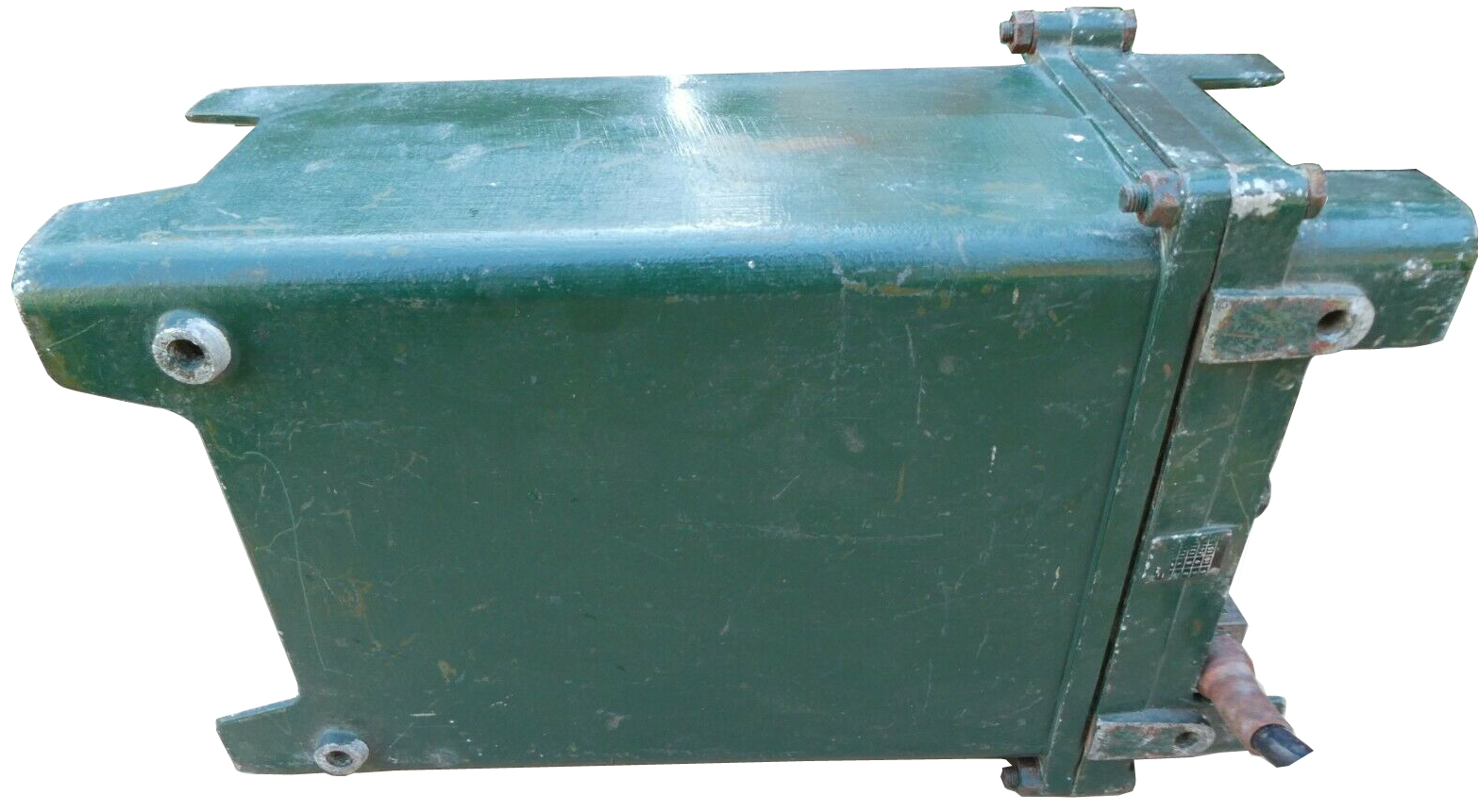
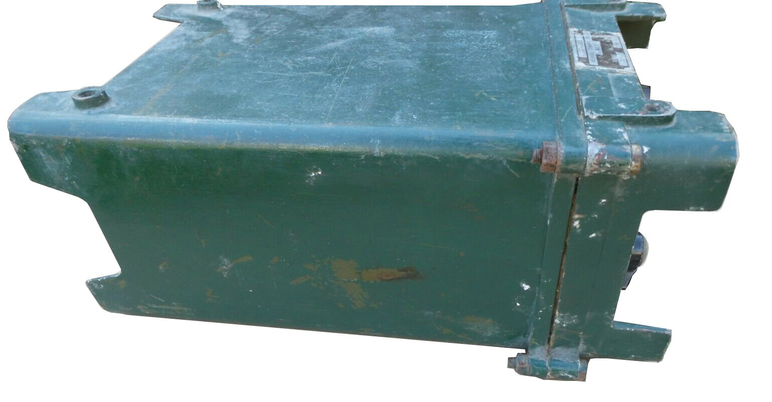
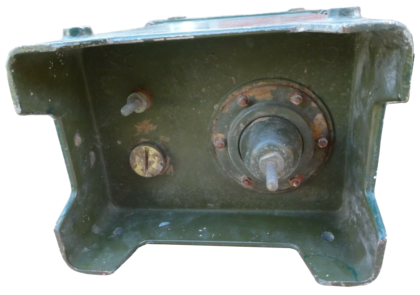
5820-99-104-3255 Support, Radio Receiver.
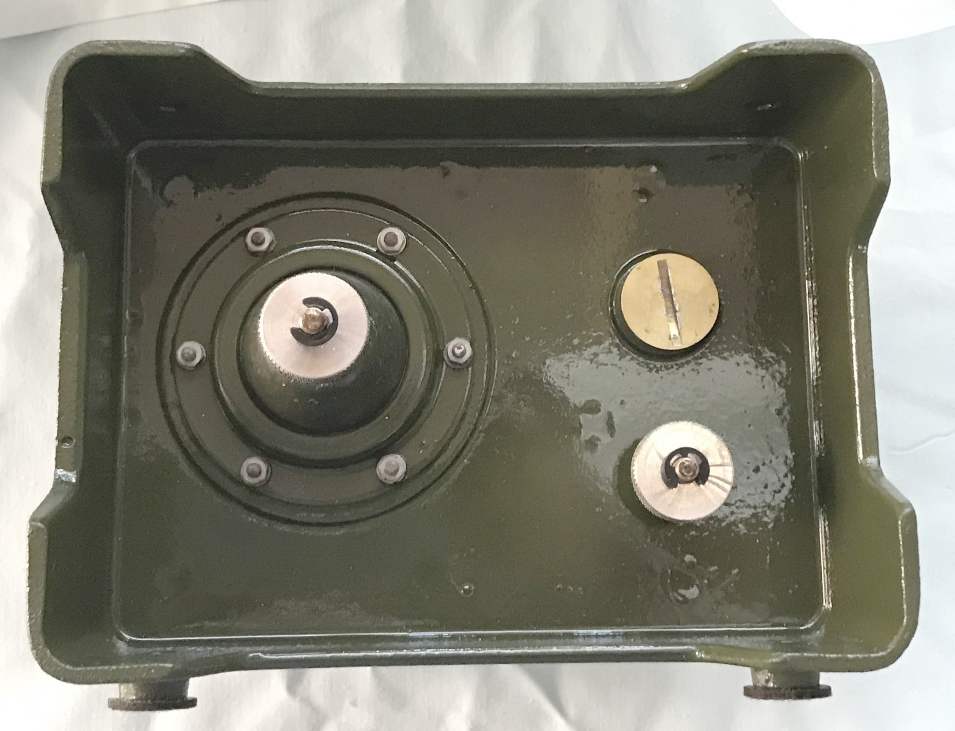
R210 Mounting Tray
Restoration of Adaptor Unit A
Reception Set, ZA 46196
27th June 2017
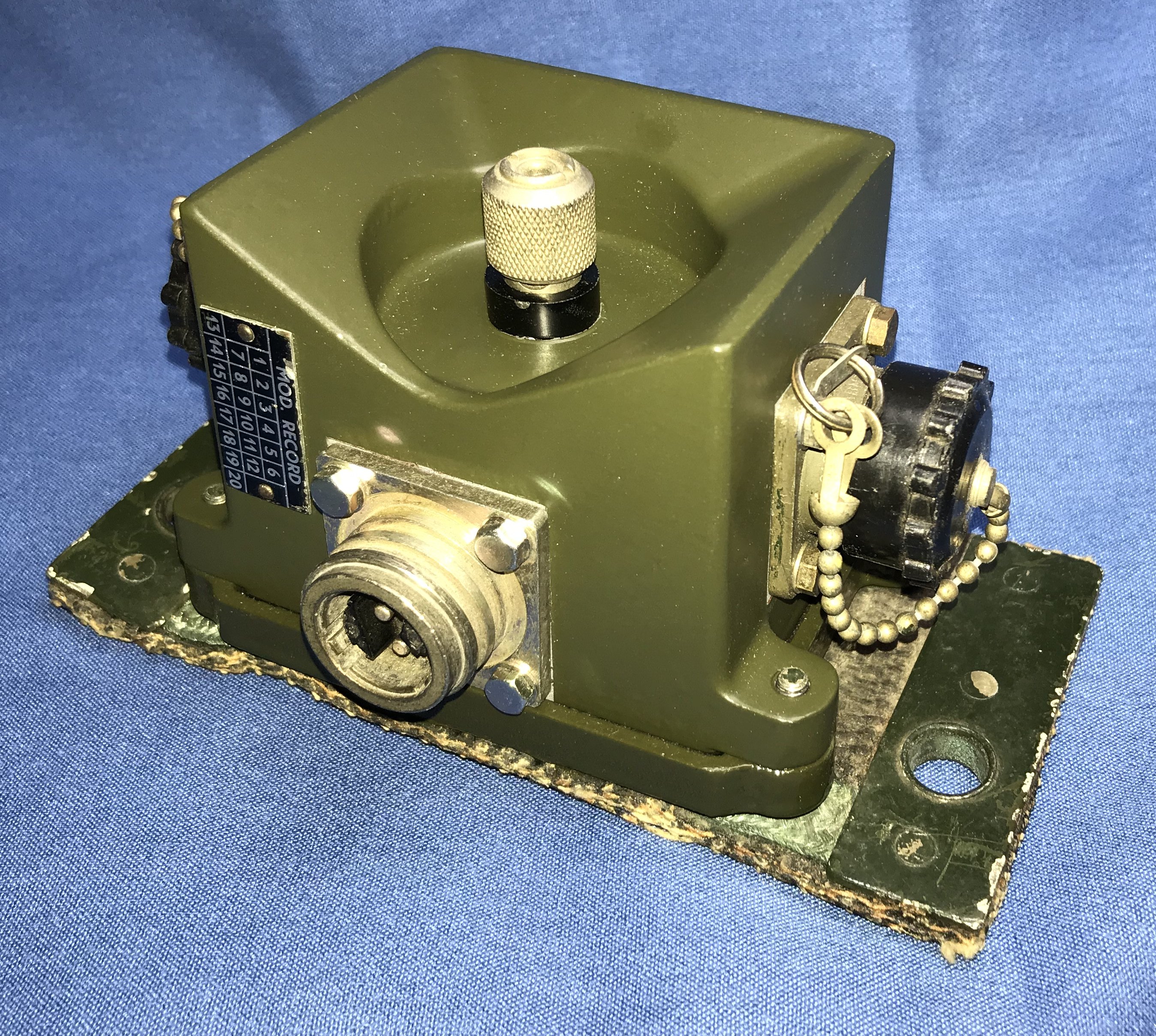

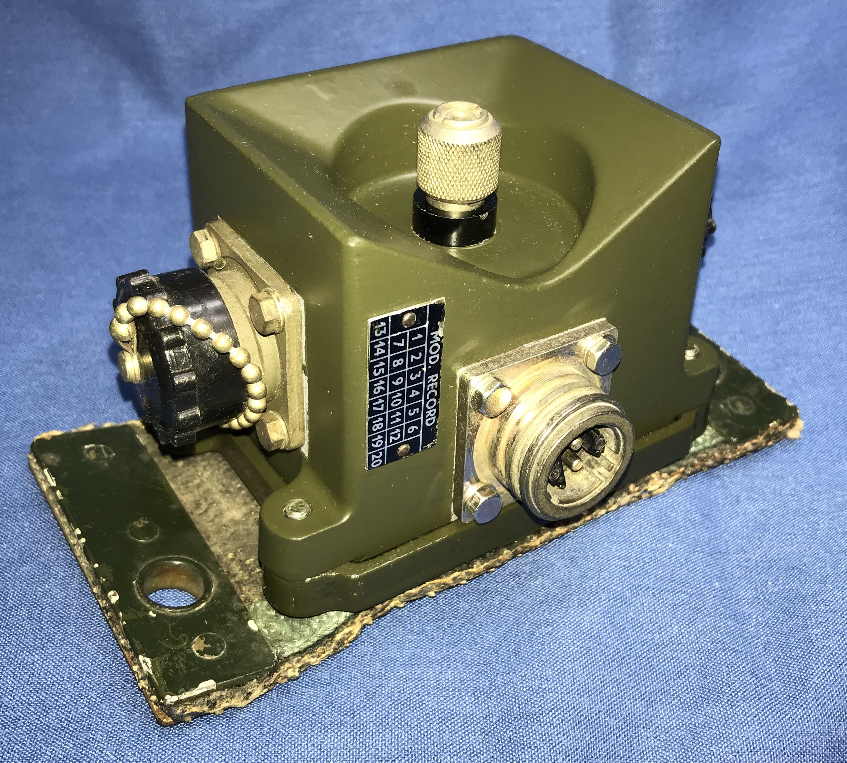
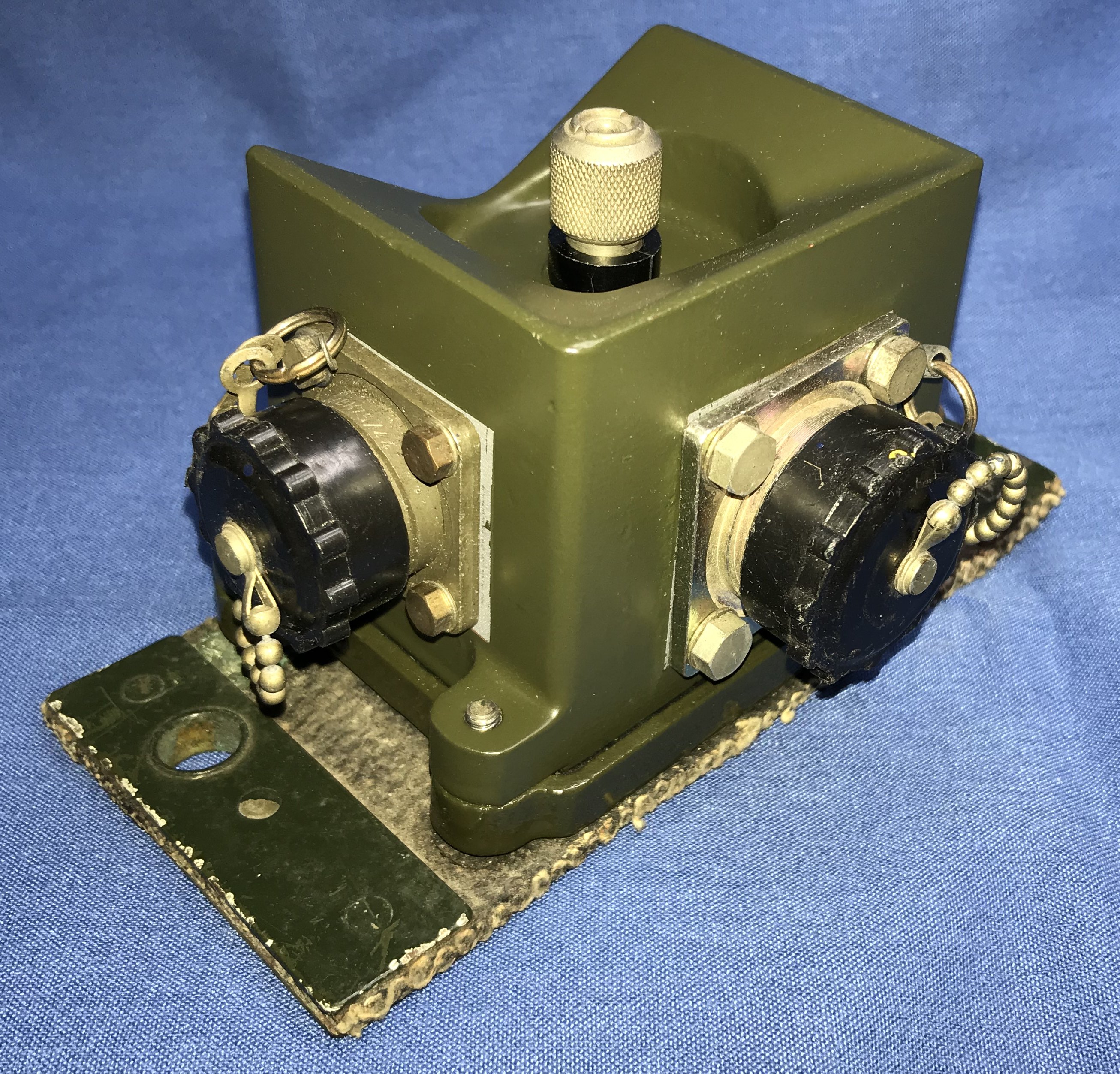
Filter Units, R.F. No.15, ZA 51404
NLE/78/08
19th July 2017
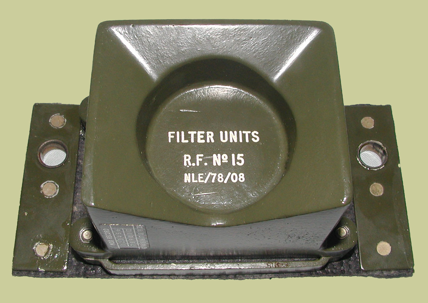
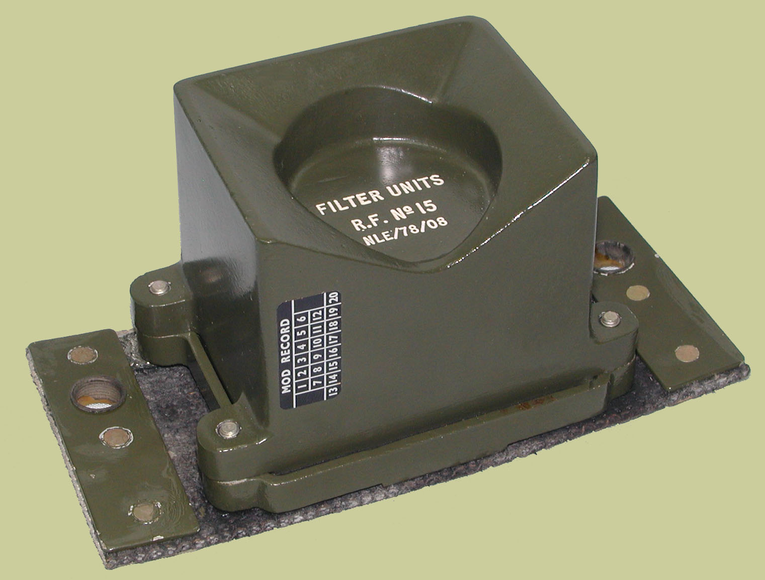
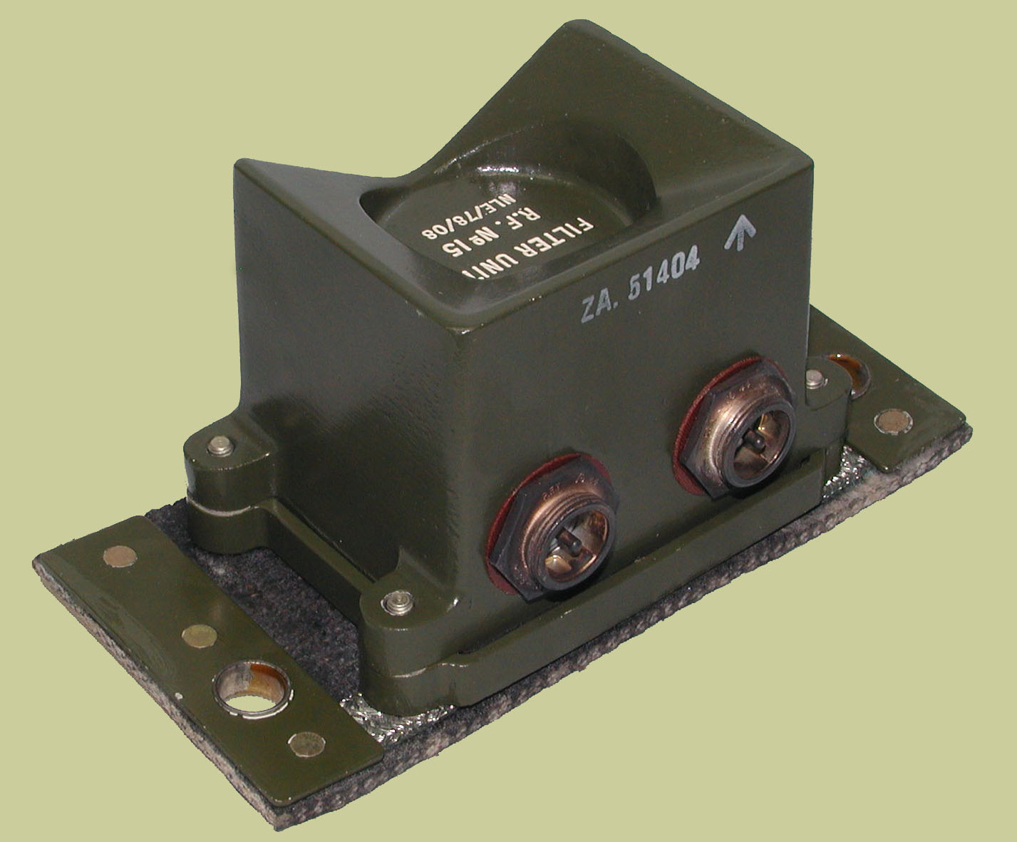
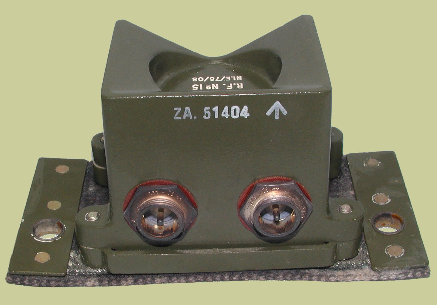
Click here to see bandwidth/insertion loss sweeps of the filter.
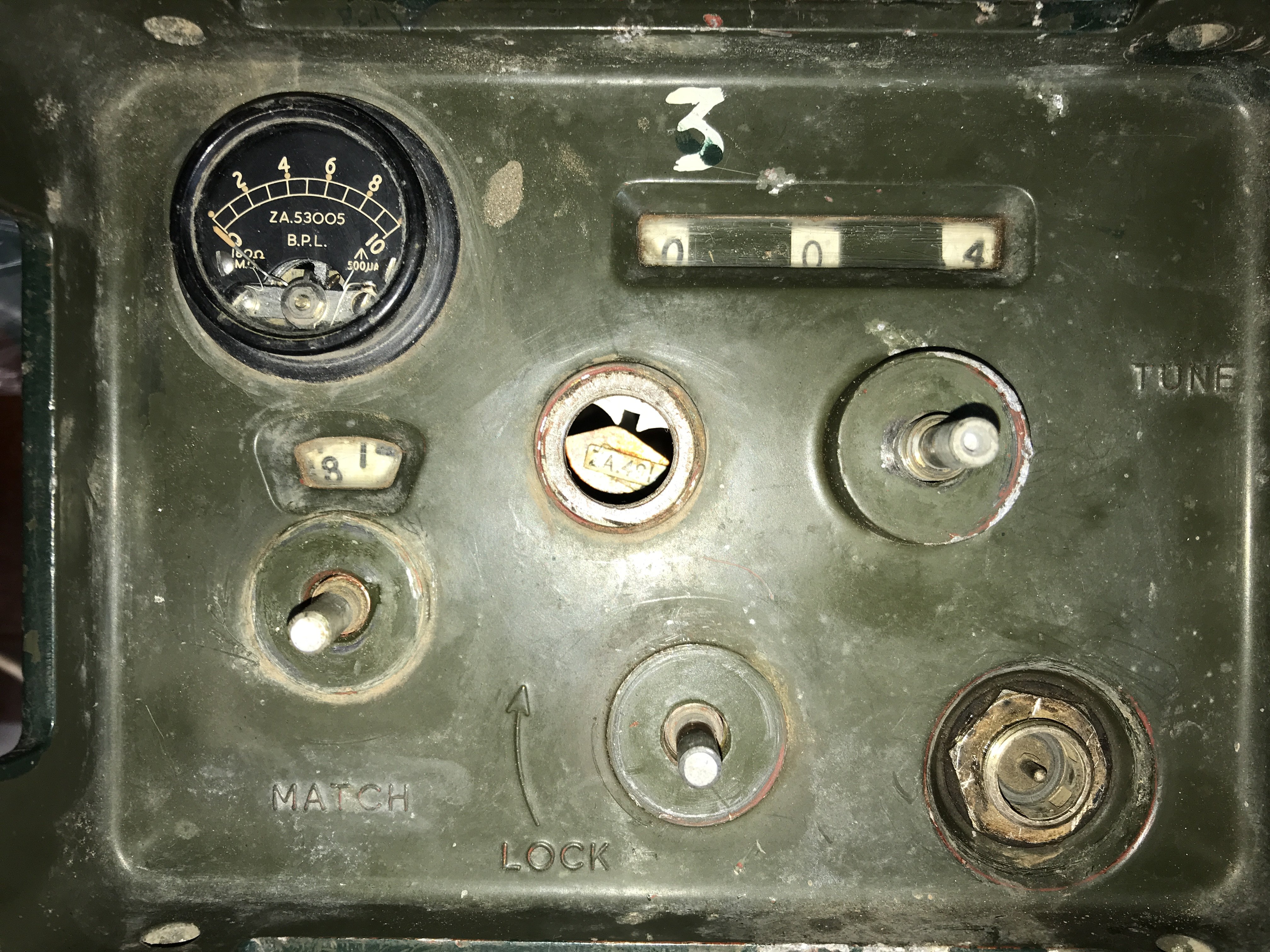
The ATU before any restoration was under taken.
Disassembly started.
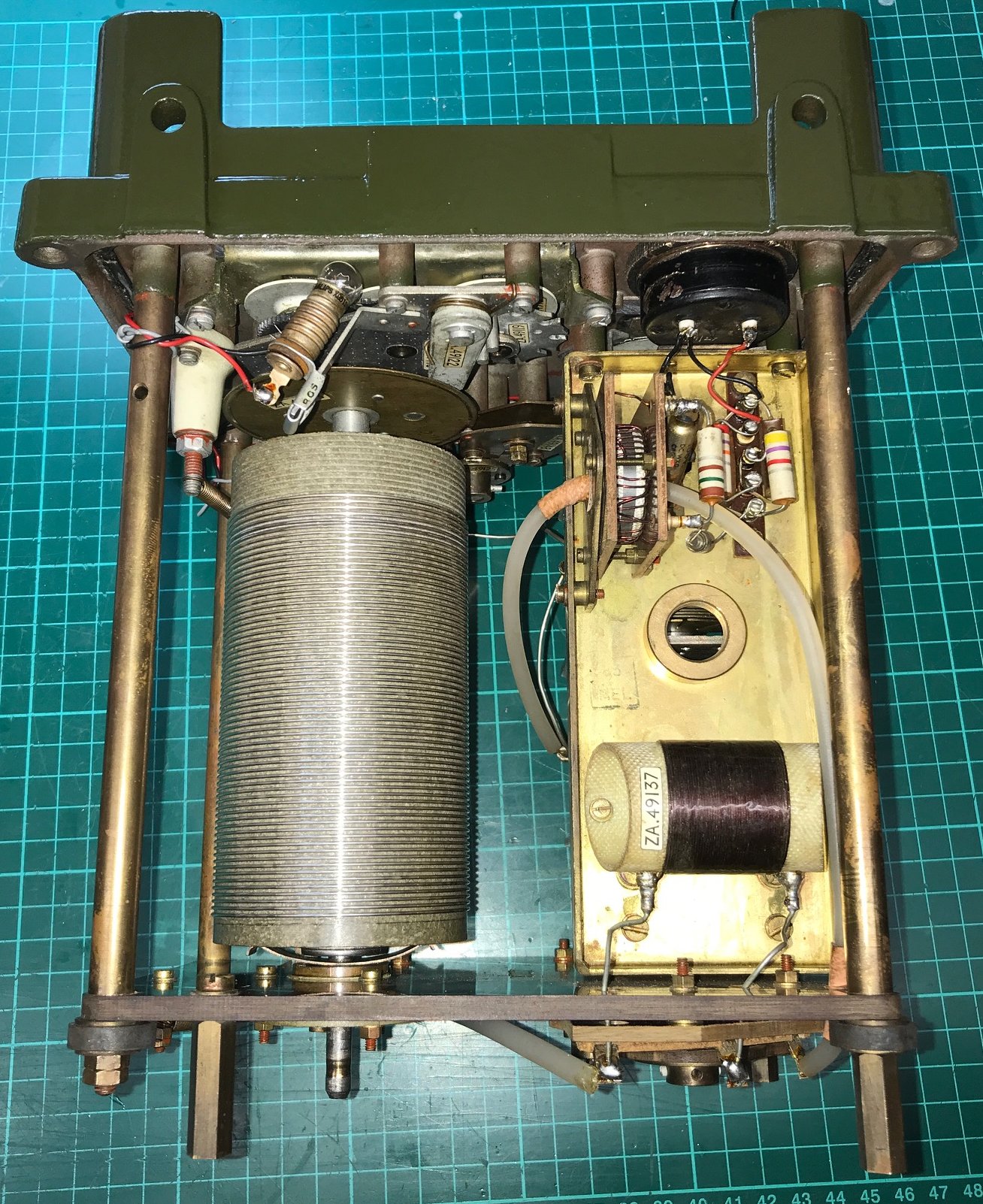
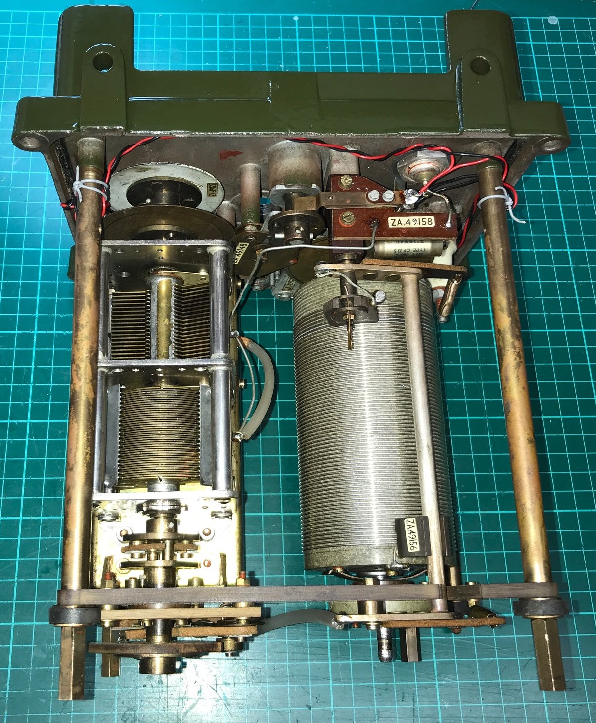
The insides of the ATU have been removed and cleaned up.
Disassembly continues.
ALL the knobs were seized on, the collet screws would not undo even with the largest of
flat blad drivers. So a little heat was applied. 250 Deg C for 3 minutes
from an SMD hot air soldering gun to each of the collet screw heads.
A very large flat blade driver and someone
to put considerable weight on the ATU
so it wouldn't move when substantial pressure
was applied to the collet screws.
A loud crack
was heard as each of the collet screws succumbed.
All the collet assemblies have been removed, washed in thinners to remove all the
old grease and dirt and re-lubricated ready to put back on later.
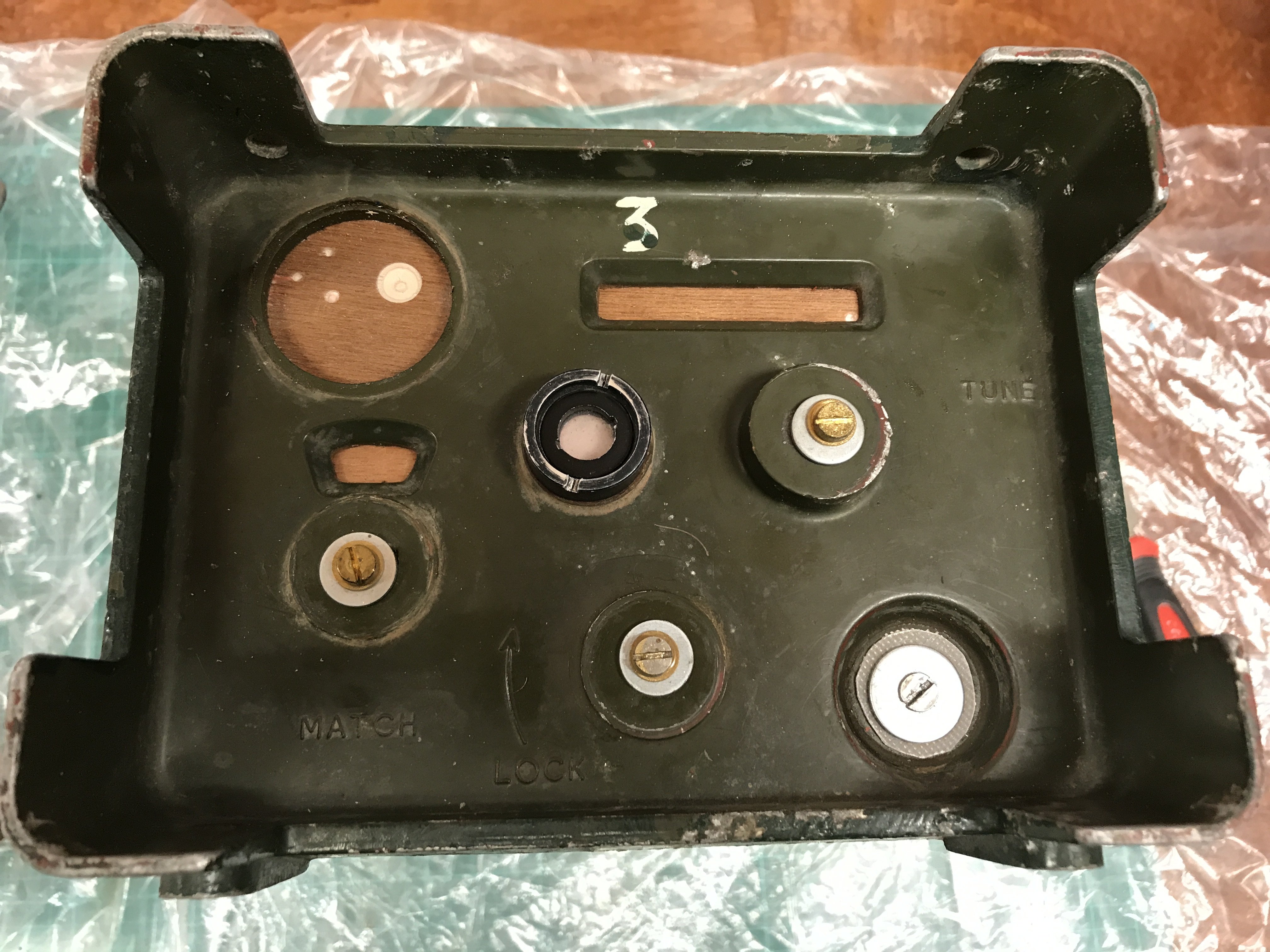
The insides of the ATU have been removed from the front
panel and case and the holes
blanked off ready for sand blasting.
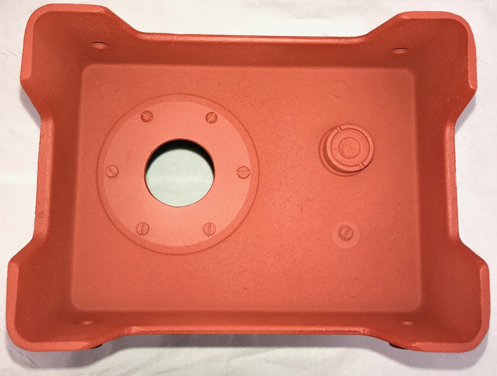
The front panel and case have been
Shot Blasted
and undercoated red oxide as it was originally.
All screw holes have blanks to stop paint going in to the threads.
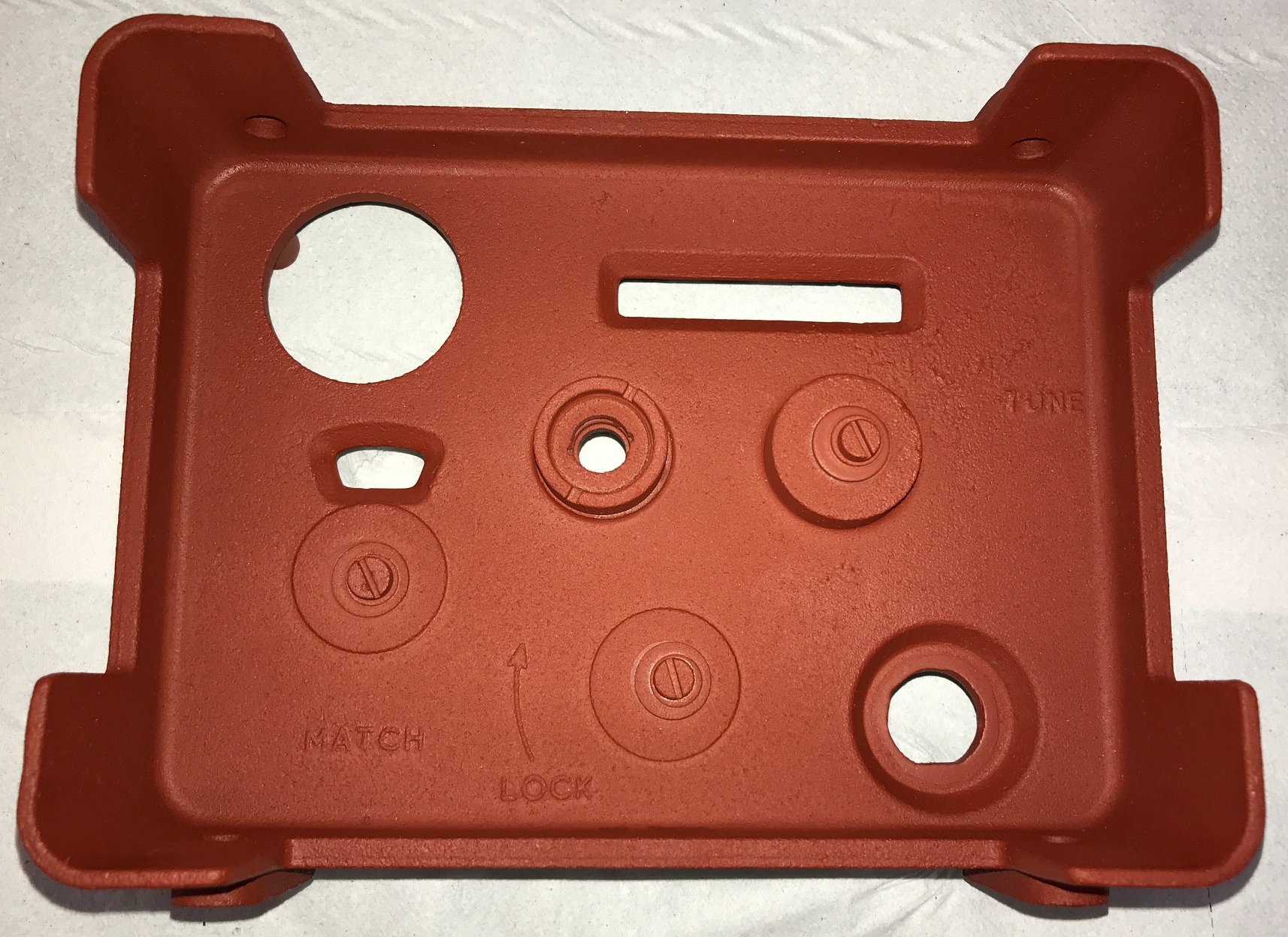
An old desiccator window has been used to blank off the desiccator/air vent holes.
Final coats of paint have been sprayed.
BS381c shade 298
Olive Drab.
Now to start reassembling the ATU.
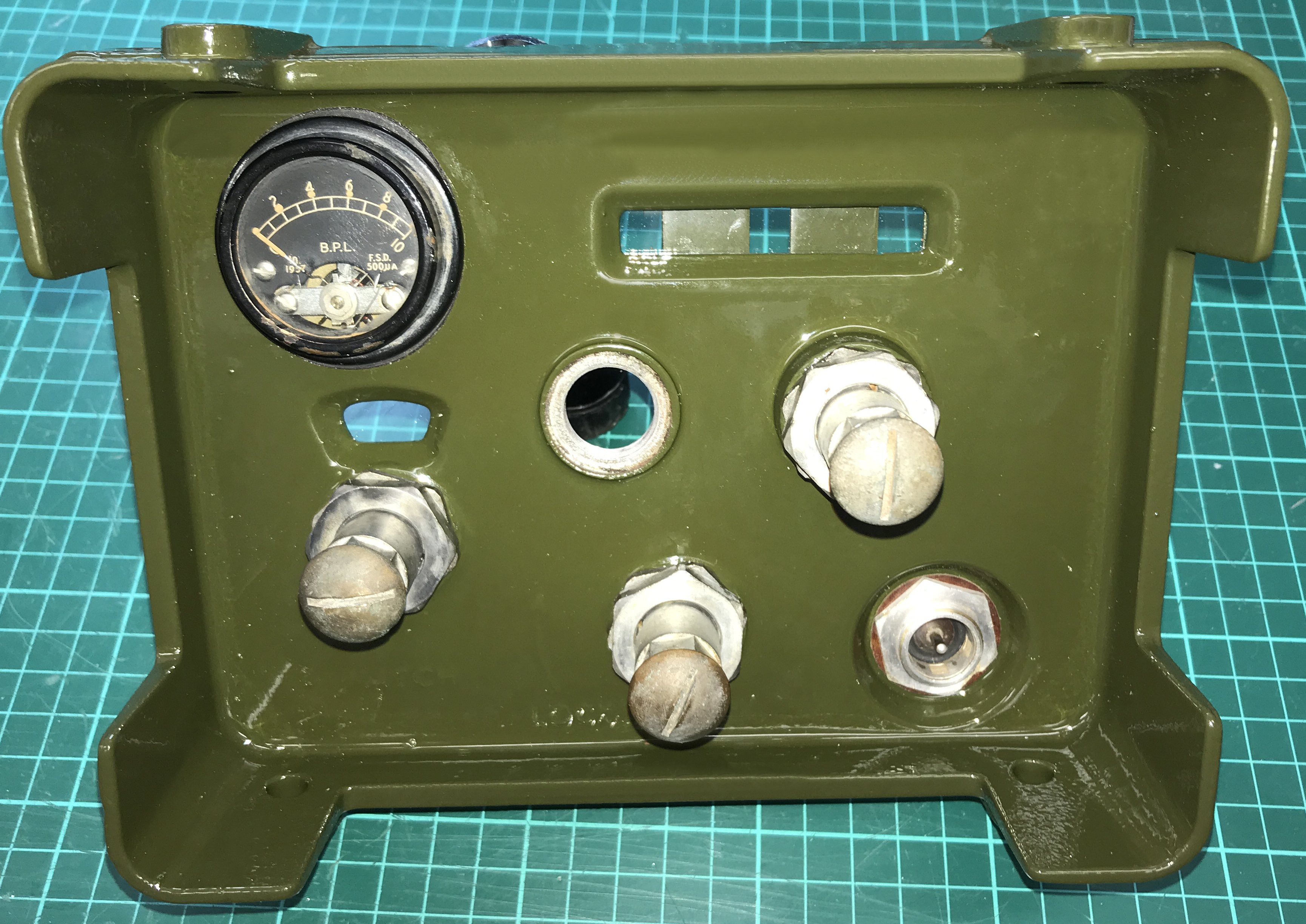
The front panel has had its final coat of BS381c shade 298
Olive Drab paint.
The original Acrylic windows were badly scratched. New Acrylic windows were made to the same
dimensions as the originals using 4 mm thick clear Acrylic.
Coax socket reattached and the meter along with the rubber seals.
The three collect assemblies fitted.
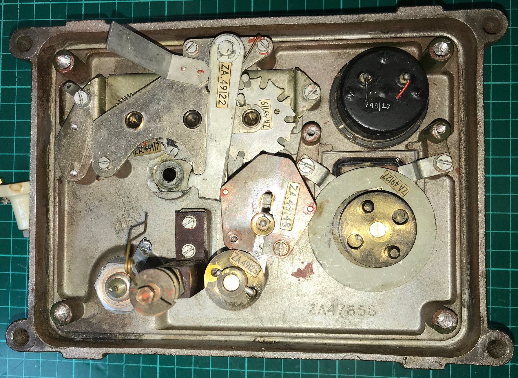
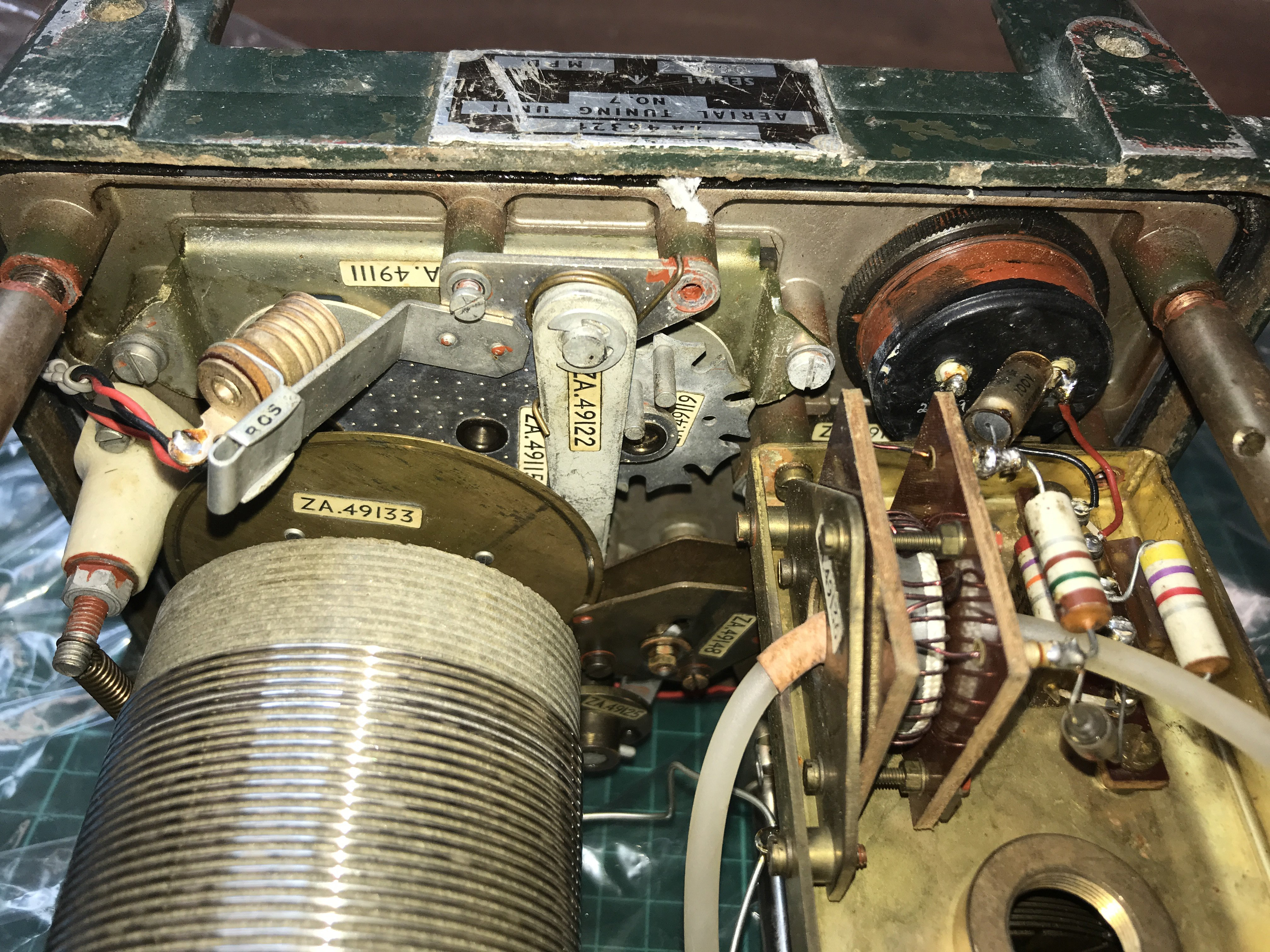
Roller coaster turns counter, variable capacitor coupling shaft and brake assembly fitted.
Variable capacitor switching on the back of the chassis.
Roller coaster and capacitor section of the chassis has now been bolted in to place.
Dial lights, meter and coax socket all wired up.
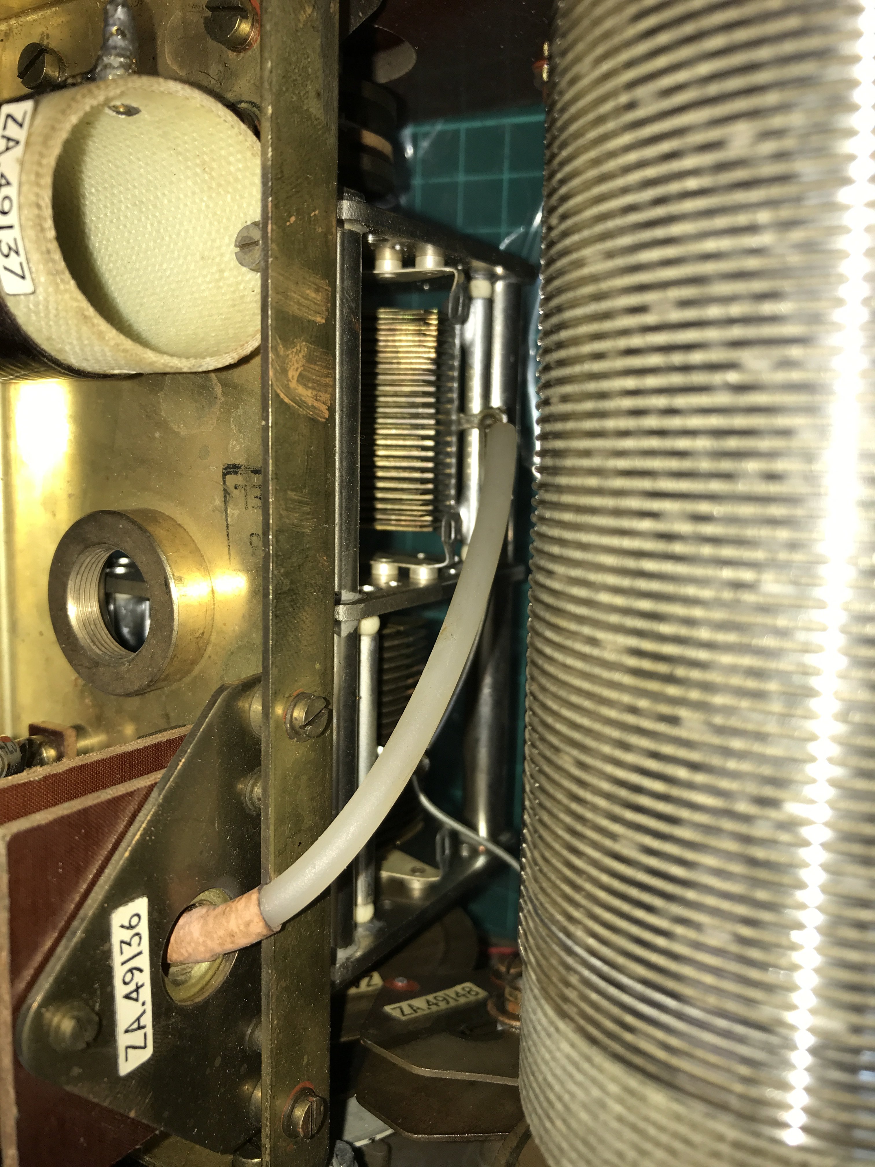
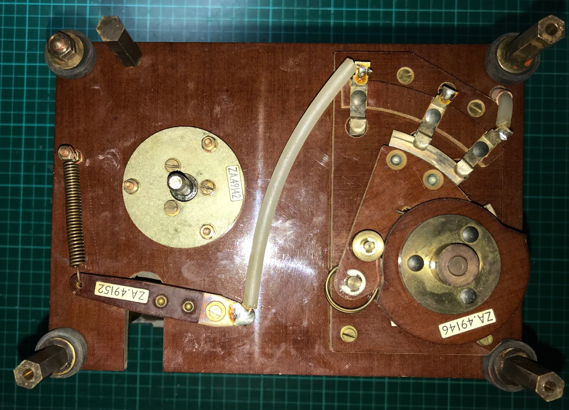
Under side of chassis. The roller coaster shorting bush and inductor pick up arm have
been put back in palace and their springs reattached.
The upper section of the brake assembly has now been bolted in place, the brake pad
clamps a brass ring
on both the roller coaster and the variable capacitor.
All that is left to do is to put the MOD and Name plates back on. On this ATU
they are stuck on, so they are easily put back in place again with adhesive.
Then dry the chsssis out and fit a new desiccator.
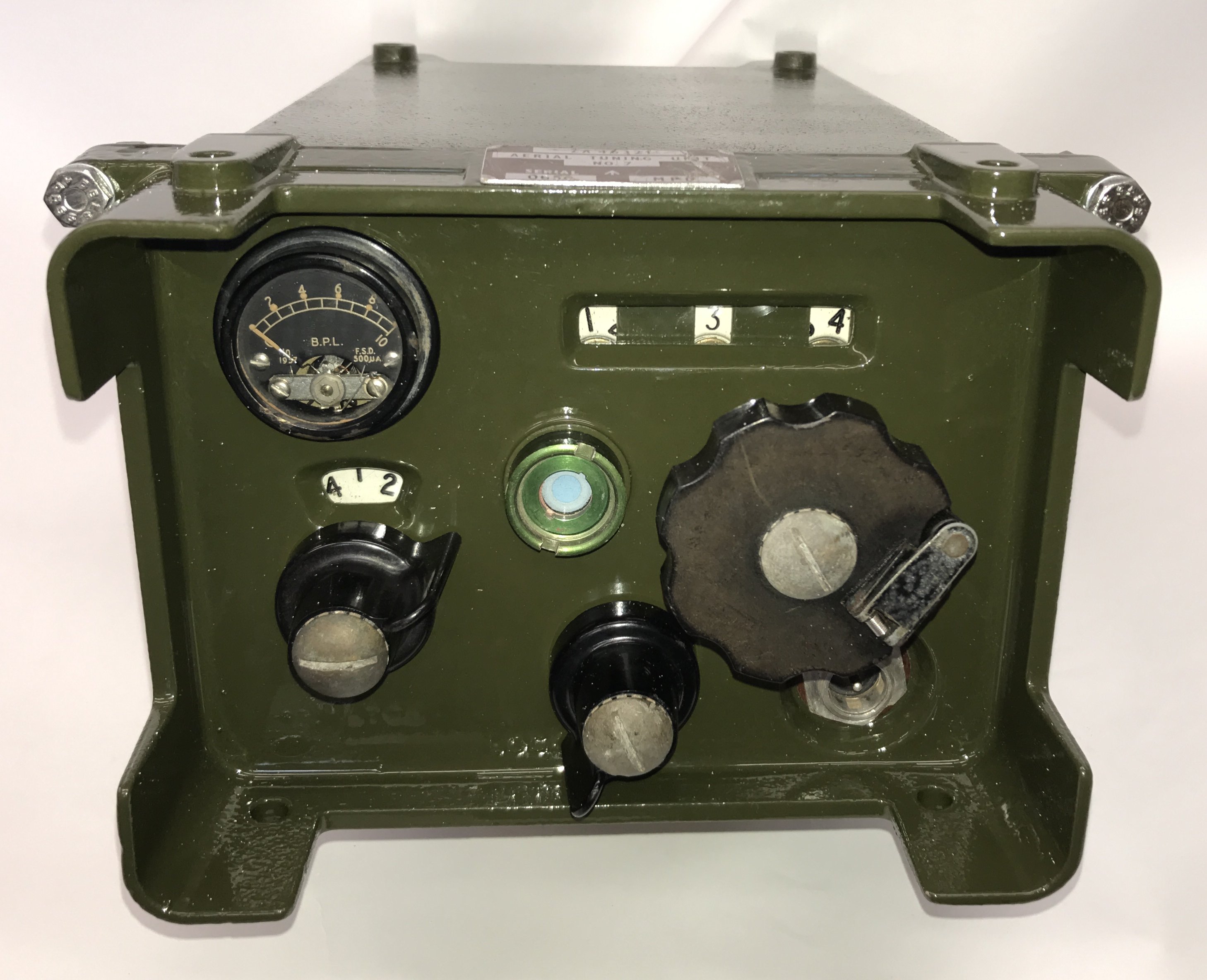
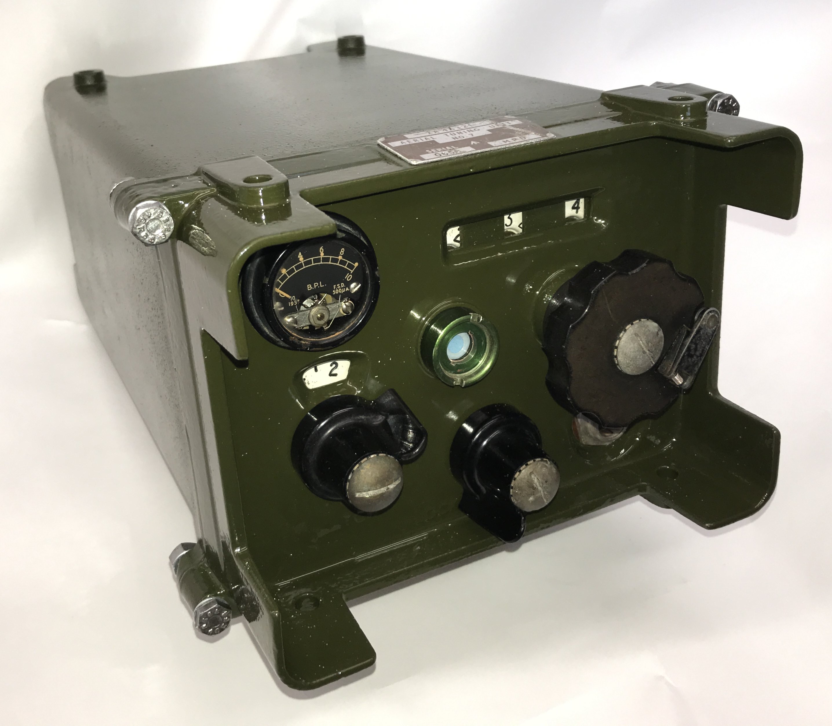
Finally the finished No 7 ATU
Thanks to Don Ross G4LOO for his work in making two replacement knurled nuts for
the Aerial and the Earth terminals. Don copied the nuts from his No7 ATU.
Click HERE to see circuit diagram of the ATU.
R210 Article writen by the late Colin MacKinnon
Site and all files are copyright © 2025 Keith Watt RN (Rtd.).