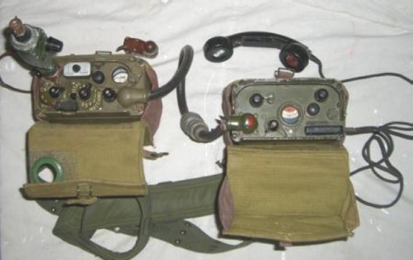
WS A510 with Transmitter on left connected via cable to the Receiver on the right.
;The antenna tuner is on the far right (not connected), above the handset. The Morse key is at the font.
|
The
Australian A510, extract from Colin MacKinnon VK2DYM's WEB site
|
WIRELESS SET A510.
WS A510 with Transmitter on left connected via cable to the Receiver on
the right.
;The antenna tuner is on the far right (not connected), above the handset.
The Morse key is at the font.
The A510 wireless set was a crystal controlled, low power lightweight transmitter-receiver, designed primarily for use by long range infantry patrols. It could be used as a man packed station on the move, in a vehicle, or as a ground station. For the ground station role, improved aerial systems were provided to achieve greater range. It operated on either voice or CW. It was powered by dry batteries which normally provided 24 hours working. The frequency range was from 2 MHz to 10 MHz.
The WS A510 was designed by AWA (Amalgamated Wireless Australasia) in 1950-51, to meet an Australian Army specification for a small waterproof HF transmitter/receiver that would have good performance in the Pacific area, i.e. from flat plains country to mountains and rain forests. The existing Army portable sets such as the UK WS No.68 and the VHF portable sets of the era were ineffective in jungle situations as well as being bulky, heavy and difficult to maintain and keep moisture free. A number of prototypes were made and tested by AWA before settling on the design.
The final A510 set consisted of two diecast boxes, one containing a four channel crystal controlled transmitter and a similar box housing the receiver and connected to the transmitter by a multi-core cable fitted with plug and socket. To compensate for aerial mistuning due to varying foliage and terrain, the transmitter was fitted with a separate aerial tuner.
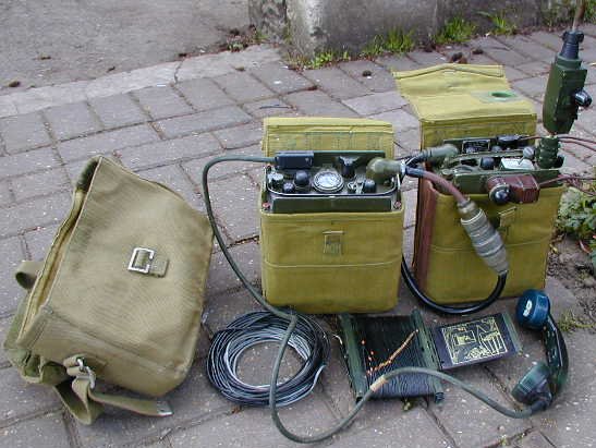
A510 EQUIPMENT.
In the above photo the satchel for the antenna wires, Morse key and handset is on the left. The Receiver is in the centre with the handset plugged into one of the two sockets. The Transmitter is on the right and shows the Antenna Tuner plugged in and the Morse key mounted. In front is the Counterpoise wire and the Dipole Antenna on a metal reel. Not shown are the metal antenna rods, counterpoise earth spike, cords aerial (throwing lines) and two batteries. The complete A510 set was supplied in a long wooden box approximately 1200mm L x 250mm W x 500mm H, with a hinged lid.
The A510 used commonly available battery valves from AWV (Amalgamated Wireless Valve Co., a subsidiary of AWA) and in the Receiver the line up was:
| V1 | CV785 | 1T4 | RF amplifier | |
| V2 | CV782 | 1R5 | Converter | |
| V3 | CV785 | 1T4 | IF amplifier | |
| V4 | CV785 | 1T4 | Reflex IF and AF amplifier | |
| V5 | CV784 | 1S5 | Demodulator and Heterodyne Oscillator |
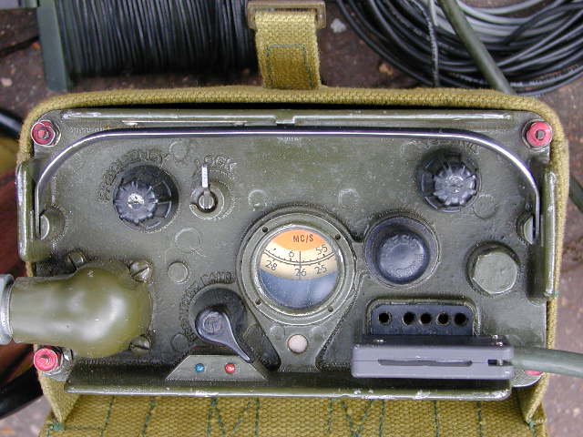
A510 RECEIVER.
The
controls are, from top left:
Tuning Knob.
Tuning Knob Lock. It rotates 90 deg. to lock the frequency.
Volume Control - at top right
Connector for cable to the Transmitter at the lower left.
Frequency Band Switch. The Blue band is 2 to 4.5 MHz and the Orange band
is 4.5 to 10 MHz.
Tuning Dial. Note that the two frequency bands are indicated by the Blue
and Orange colours.
Humidity Indicator. This is the white dot below the Tuning Dial. It is
normally blue but turns pink when moisture has leaked into the set. At that
time the set had to be replaced and repaired at base.
Dial lamp Switch. To the right of the tuning dial. It is marked "PRESS".
Seal Test Entry. This is a hexagon bolt which seals an entry for leak
testing the set.
Two Hand Set and/or Head Set Sockets. The sockets are identical.
A swivel handle can be seen at the top, to aid in pulling the set out of its
satchel.
The set is held in the diecast aluminium case by 4 nuts on threaded shafts,
shown with red paint on them.
The Receiver held the LT battery in a removable compartment underneath the set, with a short battery cable and plug.
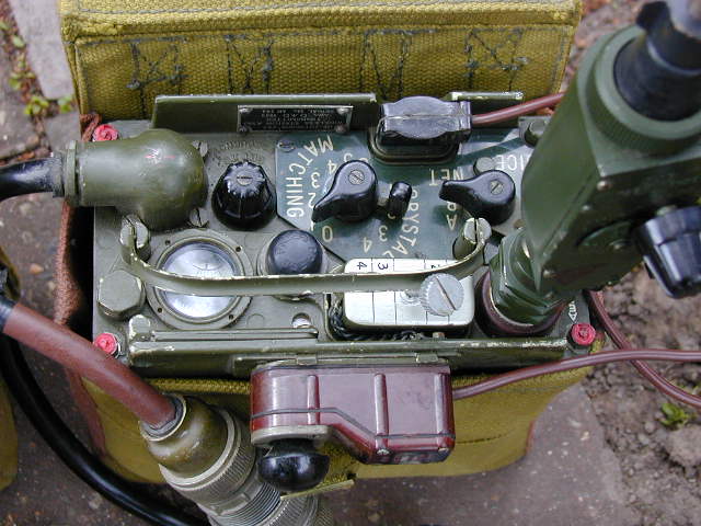
A510 TRANSMITTER.
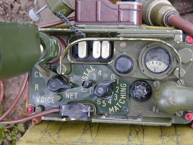
ANOTHER VIEW OF THE A510 TRANSMITTER SHOWING THE CRYSTALS.
The
Transmitter controls are, from top left:
Aerial Socket. In these photos the Rod Tuner has been plugged in. The
location of the aerial connector was to keep it as far away from the operator's
body to minimise detuning. The Rod Tuner had a 3 lug bayonet type fitting which
the operator pressed down and rotated 60 degrees to lock in position. In addition,
the centre of the socket had a press down button which gripped an aerial wire
poked into a side hole in the socket.
Crystal sockets. There is provision for 4 crystals with a small cover
to go over them. The cover is attached by a chain and held in place by a large
slotted screw.
Humidity Indicator. Normally blue but changes to pink with moisture.
It appears to be almost pink so this set needs to be dried out and resealed.
Dial Lamp Switch under the humidity indicator. This switch is a bit tricky!
It functions to light the lamps when the Function Switch is on either CW or
VOICE. It also works when the Function Switch is on R and the A-B-NET switch
is on NET.
However it also functions to test the batteries: With the Function Switch on CW and the A-B-NET switch on NET, the Lamp Switch is pressed and the meter shows the LT battery voltage within the limits of a short thick red band on the meter (see below for meter details). If below the lower end of the band the LT battery had to be replaced.
Then,
whilst holding the Function Switch on VOICE (the switch is spring loaded), and
the Lamp Switch is pressed, it shows the HT voltage on the meter, this time
against a range indicated by a long narrow red band. Again, if the reading was
low the HT battery needed replacement.
Aerial Tuning, Frequency Set and Battery Condition Meter. Within the
window is an offset frequency dial scale marked 2 to 10 (MHz) and used with
the Set to Frequency Control (see below for description). Also there is an electrical
meter used as an power output meter and a battery indicator. ;
Leak Test Entry sealed with a hexagon bolt.
Earth Terminal. Above the meter is a leaf spring which when pressed down
uncovers a countersunk hole in the flange of the case. The earth wire is poked
into the hole and the leaf spring released so that it grips the wire. The tab
on the leaf spring above the hole for the earth wire can be seen on the edge
of the case, between the meter and the seal test entry.
A-B-NET Switch. This is a concentric switch with the Function Switch.
In position A the tuning is set for a long wire end-fed aerial, at B
it is tuned for a long wire aerial, rod aerial or dipole aerial. When in the
NET position the operator can net the receiver to the transmitter.
Function Switch. There are 4 positions: OFF-CW-R-VOICE.
The R position is the normal receive position. When transmitting voice
the switch is moved and held to VOICE and is spring loaded to return
to R (receive) once released. The operator was cautioned to keep his
hand away from the aerial when operating the switch because that could cause
detuning.
Morse Key Socket. It is just below the word "NET". Inserting the Morse
key plug switched the set to CW and the key had to be removed if using VOICE.
Note how the Morse key can be clipped to the edge of the case flange for ease
of use (at top of photo). It could also be clipped to the operator's webbing.
The key is one of the smallest military keys made. (I don't count the "bell
press" button of the PRC64 as a real Morse key)
CRYSTAL Switch. This is also a concentric switch, with the Matching switch.
It has 4 positions to match the number of crystals.
MATCHING Switch. The 6 position aerial matching switch is used mainly
with long wire aerials.
Set to Frequency. A variable tuning control to set the tuning to the
approximate crystal frequency, as shown on the tuning dial of the meter marked
2 to 10.
Connector. The multi-core cable has a plug/socket connector in the middle so
that the Receiver can be coupled to the transmitter.
The transmitter also has a swivelling handle to aid removal from its pouch and
is secured in its case by 4 nuts on threaded rods in the case.
The transmitter has a battery compartment underneath, locked in place by two
large wheels, similar to the CPRC26 etc. The compartment held a 90 v HT and
-7.5V bias battery which was connected via a short cable and plug to the set.
The valve line up for the transmitter was:
| V6 | CV785 | 1T4 | Mod. Audio Oscillator. | |
| V7 | CV807 | 3A4 | Xtal Oscillator | |
| V8 & V9 | CV807 | 3A4 | In Parallel Power Amplifier |
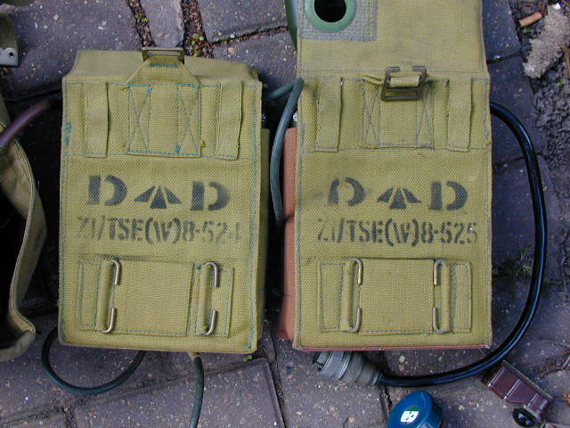
SATCHELS FOR THE A510 TRANSMITTER AND RECEIVER.
The transmitter (in the right hand pouch of the above photo) was carried on the left side of the operator, clipped to his standard webbing belt. The receiver balanced that on the right side of the operator. They were positioned generally on the front of each hip.
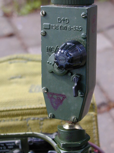
A510 AERIAL ROD TUNER. It has a ball joint at the base to allow the
whip to be swung to a convenient angle.
To ensure efficient operation in the widely varying terrain, it was found critical to use an aerial tuner when using the 8 foot metal antenna rod. I suspect that the separate aerial tuner was added after field trials showed that the internal aerial matching circuit was insufficient. However, all field test reports available include the aerial tuner as part of the set so perhaps it was an original design feature. The tuner has a locking device (lower right) and a tuning knob with a frequency scale covering 2 to 10 MHz. In operation the operator rotated the knob while watching the meter for maximum deflection, then locked the knob in position.
The eight foot aerial rod was in plug together sections with a nylon cord inside to facilitate lining up the sections.
The Counterpoise could be used with the rod aerial. It consisted of 4 black wires joined together by the counterpoise stake and laid out to form a cross. The stake was driven into the ground and a green earth wire went from there to the earth terminal on the transmitter.
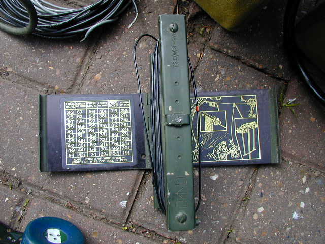
A510 DIPOLE ANTENNA ON METAL REEL. Note the red marker sleeve on the wire.
To cover various applications the A510 was supplied with several aerials. Apart from the 8 foot rod aerial used with the Rod Tuner there was an adjustable 135 foot end fed aerial and a 136 foot dipole with a coaxial cable feeder.
The end fed aerial consisted of 8 black leads of varying calculated lengths, fitted with a hook at one end and an eye at the other and numbered one to eight. The far end had a small insulator which could be attached to one of the cords aerial (a nylon throwing line). The set was supplied with an instruction card detailing the sequence of leads needed to be joined together (hook to eye) to match a frequency. There was also an orange lead which attached between the transmitter aerial socket and the first of the black aerial leads. The counterpoise was used with the end fed aerial.
The dipole aerial shown in the photo above consisted of two aerials, lightweight, 68 feet and one 70 ohm aerial feeder plus the two aerial cords. The aerial was wound on a metal reel that included two protective metal flaps with calculated lengths for each frequency band and assembly instructions as shown. Each of the two dipole leads was marked every 12 inches with a red marker so the operator could measure out the correct lengths ; for the ; required frequency. It was suggested that the aerial be no more than a quarter wave (half the aerial length) above the ground.
The photos for this article were supplied by Phil Rhyder from UK, for which I am most grateful. My own A510s are stuffed away in storage and I can't get to them.
The
officer normally used the handset. The operator could use a headset, with two
headphones and a microphone connecetd by an acoustic tube. the tube was found
to be easily broken, so a second headset was introduced, using a boom mounted
microphone.
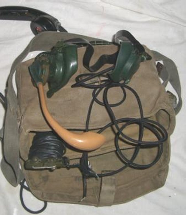
A510 HEADSET. Early type with acoustic tube.
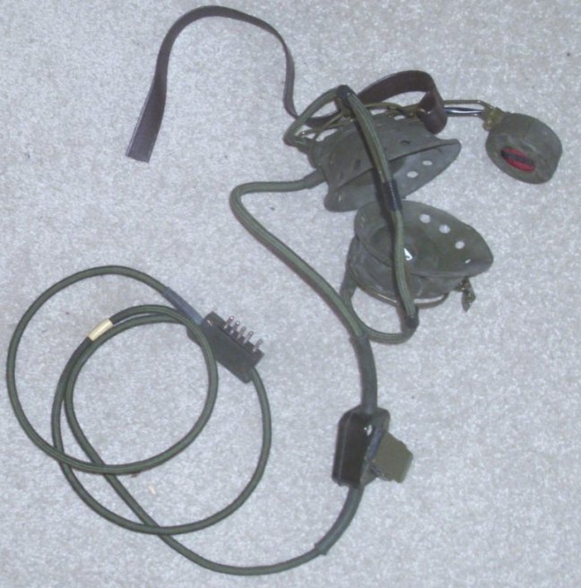
A510 HEADSET. Later type with boom mounted microphone.
The LT battery and HT battery were different sizes.
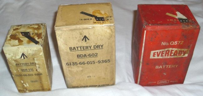
A510 BATTERIES. Left is the LT
battery (1.5V). Right are two types of HT battery (90V and -7.5V).
A510
DOCUMENTATION
Please note, this article is copyrighted.
Documents
and text reproduced here with
kind permission of Ray Robinson VK2ILV
Colin
MacKinnon
1941 - 2004
We all miss you Colin!
Ray still maintains Colin's WEB site,
which can be found at - http://www.qsl.net/vk2dym/