732WS19 ws19 19 set wireless set 19 wireless set no19
WS19,
WIRELESS SET NO 19, 19 SET, WS18, 18 SET, WS22, 22 SET, WS38, 38 SET
The
Wireless-Set-No19 Group
Royal Signals
www.royalsignals.org.uk
Restoration of a Power Supply Unit No.5
Project description.
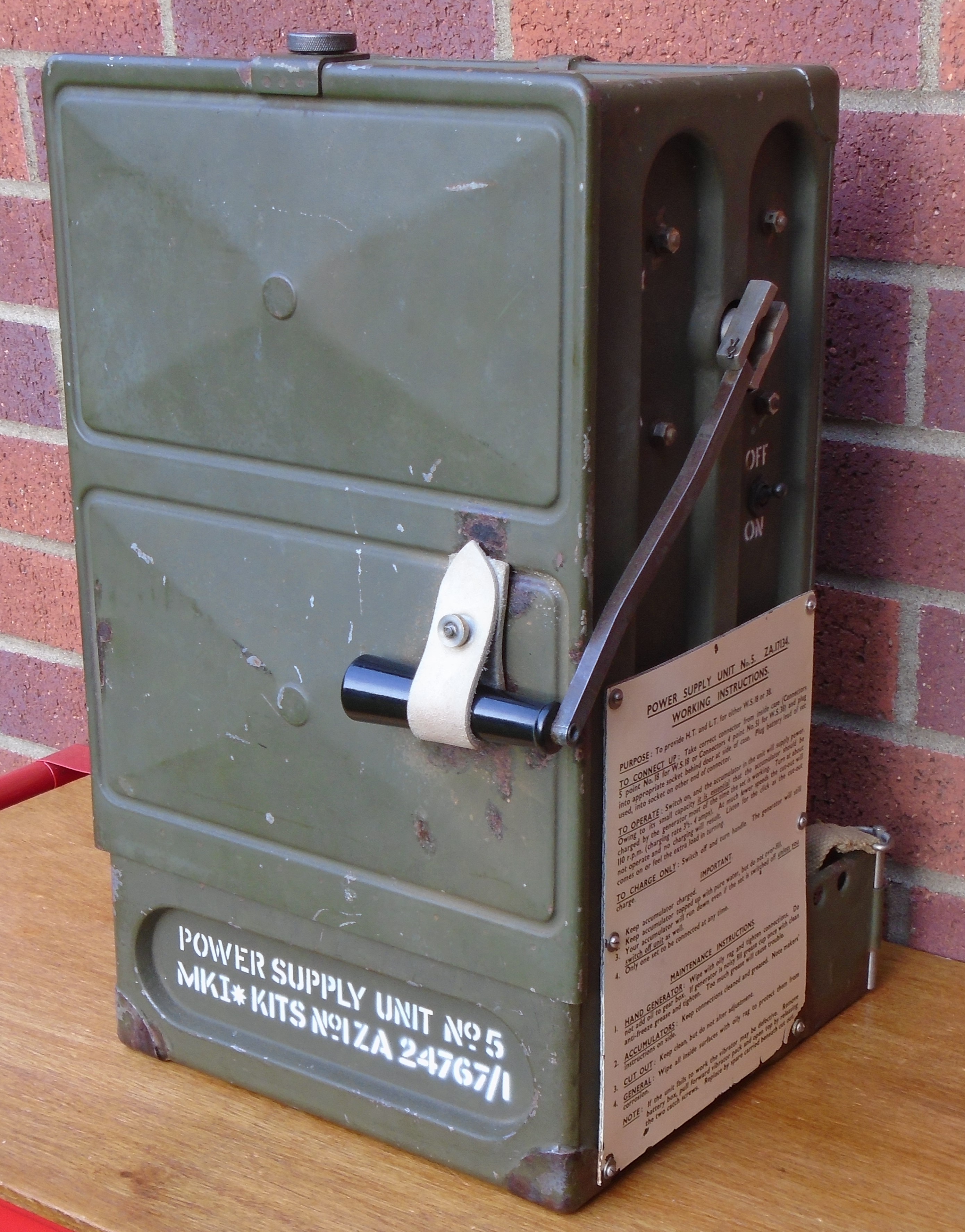
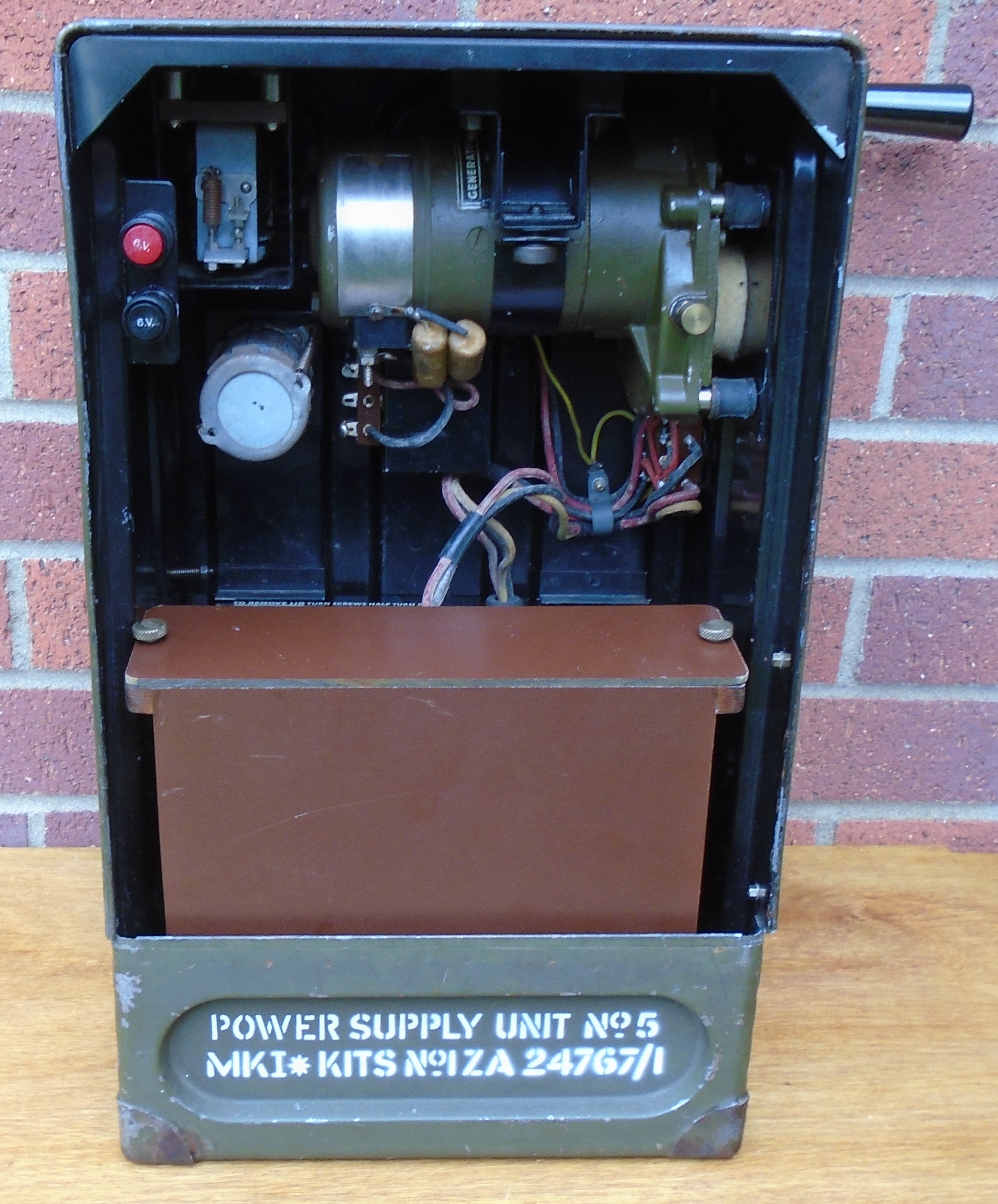
The power supply came from a friend, now sadly SK. It had been sitting around for a long time, since neither the author, nor his friend had a WS18/68 with which to use it. The author does have a couple of WS38s which had been used with a replica battery in the past, but there seemed no pressing need to use the PSU No.5. The acquisition of a WS48 provided the nudge to restore the PSU, and see if it could also power the WS48, the American equivalent to the WS18. Figure 1 shows the power supply unit.
PSU description.
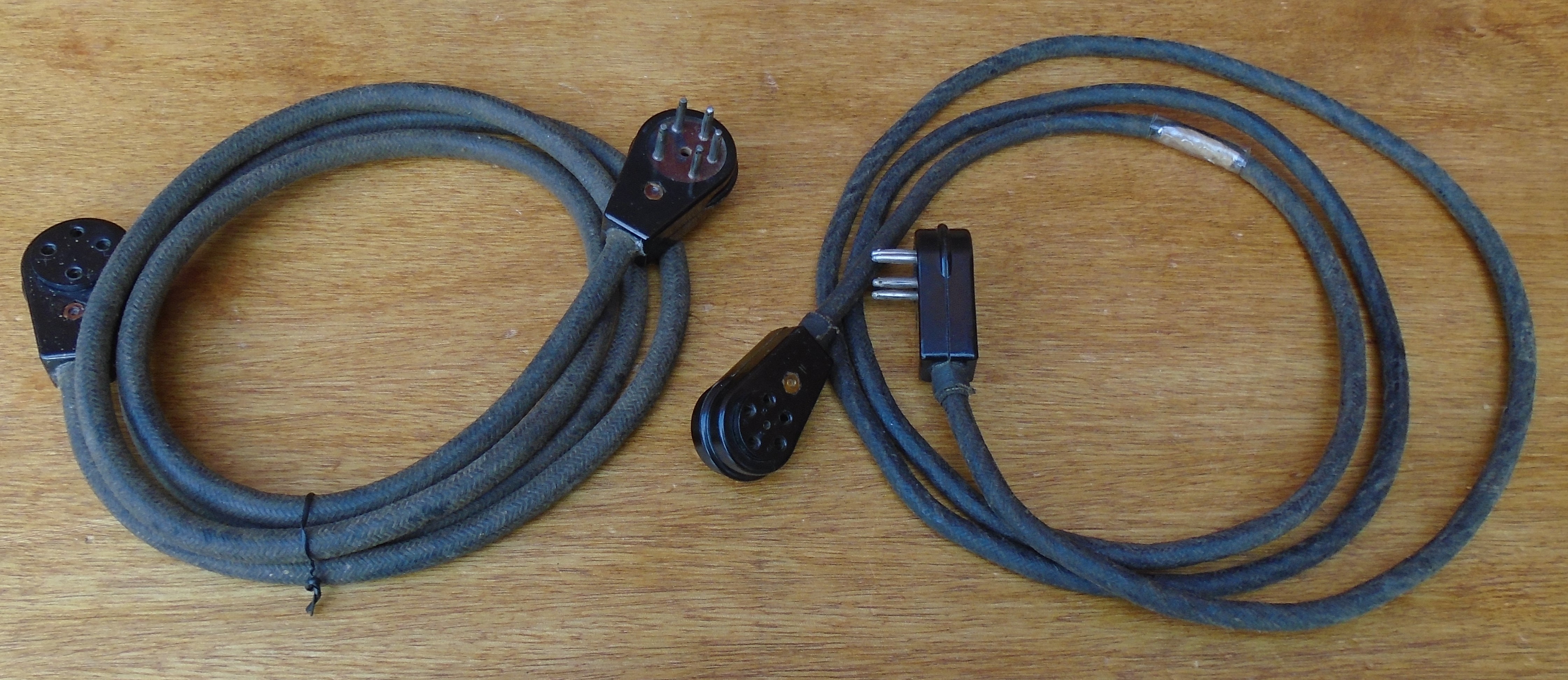
Power Supply Unit No.5 contains a 6 Volt lead acid battery which powers a vibrator power supply, Supply Unit Vibratory No.5. This unit provides 150 Volt HT, 3 Volt LT and 12 Volt bias supplies to run the WS18/68. For the WS38, the 12 Volt supply is not used. The battery and vibrator unit are housed in a steel case, quite similar to the WS18 case, and fitted with similar brackets on which to mount a carrying harness. Also fitted within the case is a hand generator used to charge the battery and simultaneously run the set. The vibrator power unit, Supply Unit Vibratory No.5 is housed within its own case, inside the main body of the unit. Figure 2 shows its location. The original battery consisted of three Accumulators, Lead Acid 2 V, 14 Ah, Type B. These were connected in series to provide 6 V and fitted into a moulded battery box fitted in front of the Vibratory unit. The accumulators and box were missing from the author's example, but all other parts were present and unmolested, including the two supply leads used to connect the supply to either a WS18/68 or WS38, Figure 3. The leads plug into sockets on the left-hand side, and are covered by a plate when not in use. A separate cover fits over the front of the unit to protect the contents, and hold the battery box from moving about when carried. For normal operation, the cover can remain closed. Printed operating instructions are included on the right-hand side of the main cabinet.
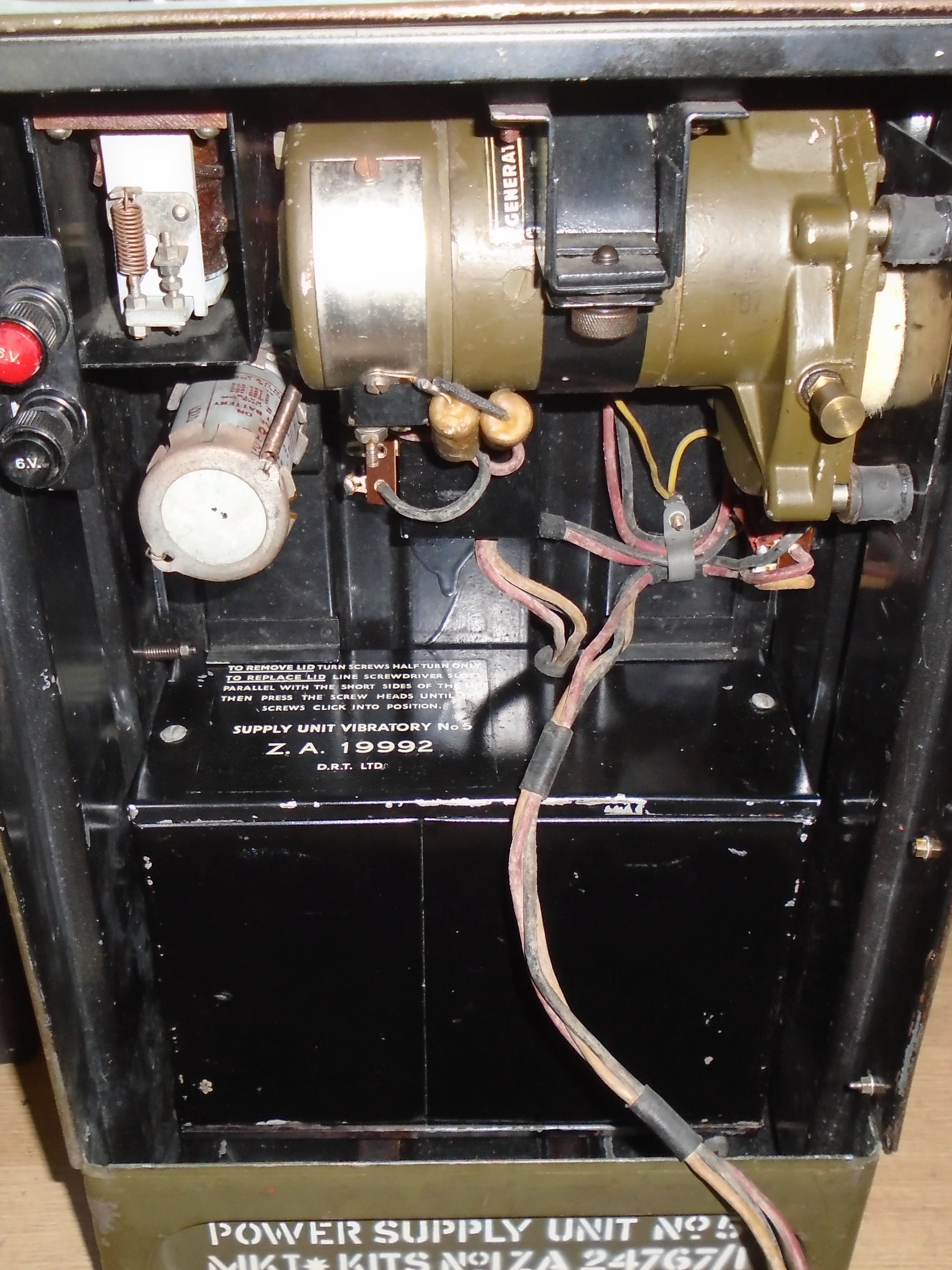
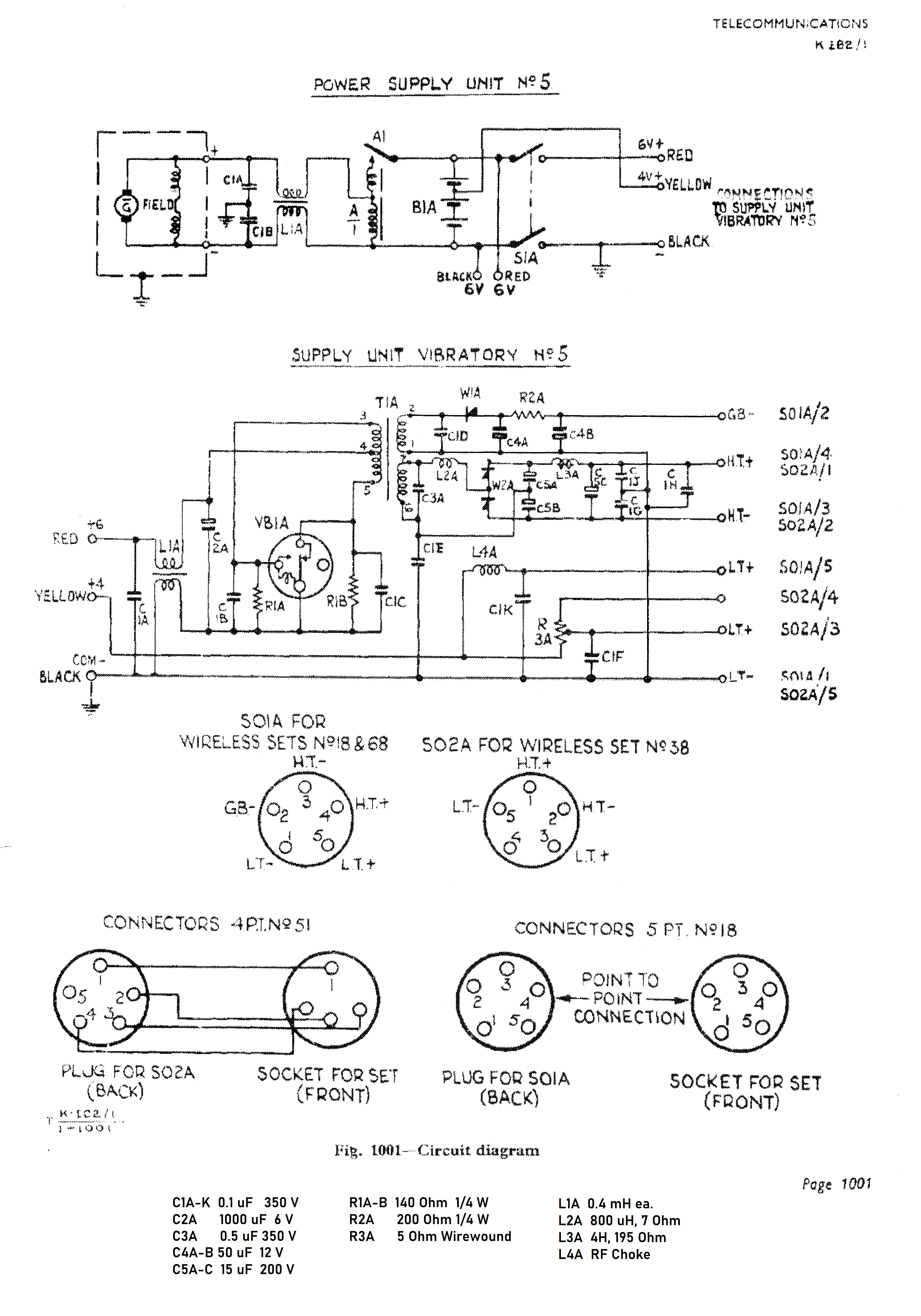
The hand generator has a rated output of 5 A at 6 V at about 100 - 110 r.p.m. of the cranking handle, sufficient to fully run the transmitter and charge the battery at the same time. The generator is connected to the battery by a cut-out relay, to ensure it is only connected to the battery once spinning fast enough to charge the battery. The relay is located top left in the case, beside the generator, and just above a spare vibrator, also mounted in the main case, Figure 2. Two additional terminals visible in the photograph provide the facility to charge an external battery. An on/off switch near the generator handle connects the battery to the vibrator power supply, and switches the unit on. The crank handle folds down when not in use, and is secured to the removable front of the case via a leather strap. Figure 4 shows the power supply and vibratory unit circuits, courtesy The Wireless Set 19 Group, Royal Signals [1].
LT for the radios was supplied via a 4 V tapping on the accumulator bank, together with a dropping resistor for the WS38 or a choke for WS18, located within the SUV No.5. For the WS38, the dropping resistor, R3A, is arranged as a potentiometer, with the plug connected to SO2A having a link between pins 4 and 5. The step up transformer within the SUV provides two output windings, one for the 12 V bias supply, and one for the 150 V HT supply. The 12 V bias supply uses ½ wave rectification using a selenium rectifier and simple resistance-capacity smoothing. The HT supply uses two selenium rectifiers in a voltage doubling circuit with choke-capacity smoothing.
Restoration.
Cosmetically the unit was in quite good original condition with some scuffs and scratches as might be expected, and the odd patch of surface rust. The unit was given a good clean, both inside and out with soap and water. There was an area of surface rust on the cover plate, behind the leather strap which holds the crank handle. No doubt the leather had served to help retain moisture in that area. Another patch of surface rust was present on the left had side, where repeated opening of the socket cover had worn some of the paint off. Neither area of rust was serious, but they were treated with a rust stabilising solution to prevent further deterioration. A snap fastener which holds the crank handle in the leather strap when not in use had corroded and disintegrated. The snap fastener was replaced by a nut and bolt, together with a large knurled nut which served to hold the handle in the strap when not in use. The plain steel crank handle which showed some surface rust, was buffed up on a rotary wire wheel. No other restoration of the case was carried out as this was felt unnecessary.
Generator.
This was in very good clean condition, and the crank handle turned freely. The main and intermediate drive gears are made from laminated plastic material to reduce noise and the amount of lubrication required. The little grease Stauffer on the gearbox was refilled and screwed down a couple of times to inject a quantity of fresh grease into the gears. When tested into a dummy load of about 1 Ohm, the generator would provide the 6 V at 5 A depending how hard the crank was turned, so seemed to be working fine. The cut-out relay seemed to operate correctly, dropping out at low speed and preventing discharge of the battery into the generator.
Supply Unit Vibratory No.5.
The author likes the good old fashioned mechanical vibrators, but these normally need a bit of work to get them going, assuming they are not past redemption due to worn/burnt out contacts. For those not in favour of the mechanical variety, suitable solid state replacements are available from The Wireless Set 19 Group [2].
The vibrator used in the supply unit is a standard 6 V, 4 pin, non-synchronous type. The author has resurrected many of these in the past. The base seal was carefully prised open using a screwdriver and with the help of a long nose pair of pliers. This allowed the base together with its vibrator to be pulled from the bottom of the can. Luckily, the contacts were not significantly worn or burnt, just covered in a dark grey/black material, probably some sort of oxide, as expected. The method used to clean the contacts, and which might not be recommended by others, is to remove the two securing nuts at the base of the vibrator mechanism, then carefully pull all the pieces off the securing bolts, making a note of how they were assembled. The contacts, with a bit of manipulation, can then usually just be held against a rotary wire brush one at a time. The deposit is extremely hard and it can take a minute or two to remove it all, leaving a contact that is clean and smooth (To the naked eye at least). If any of the contacts have any projecting ridges, caused by arcing, then these are very carefully ground off flush with the remaining contact. The mechanism is reassembled making sure the contacts line up squarely and the operation of the contacts checked.
After cleaning and reassembling, the bare vibrator was plugged into a test rig, where it is easy to see the contacts (This would not be so easy in the Supply Unit itself without some sort of extension lead, as the vibrator is mounted low down in the case). The test rig also provides a load on the output from the vibrator. Some vibrators have an adjustment screw which sets the correct position of the reed, others just rely on slight bending of the contacts to affect correct positioning. There is a certain amount of trial and error required here to get the vibrator to operate every time, and produce a good output while consuming the least current. With the refurbished vibrator running well, the spare vibrator mounted in the main case, was given the same treatment. The cases were popped back on, but the bottoms were not re-crimped. From experience, the contacts may well need a bit of a clean again in future. This is easy if the unit can just be pulled from the case without prising the seal apart again. Of course a solid state vibrator would dispense with all this messing about. One of the now operational vibrators was plugged back into the SUV chassis.
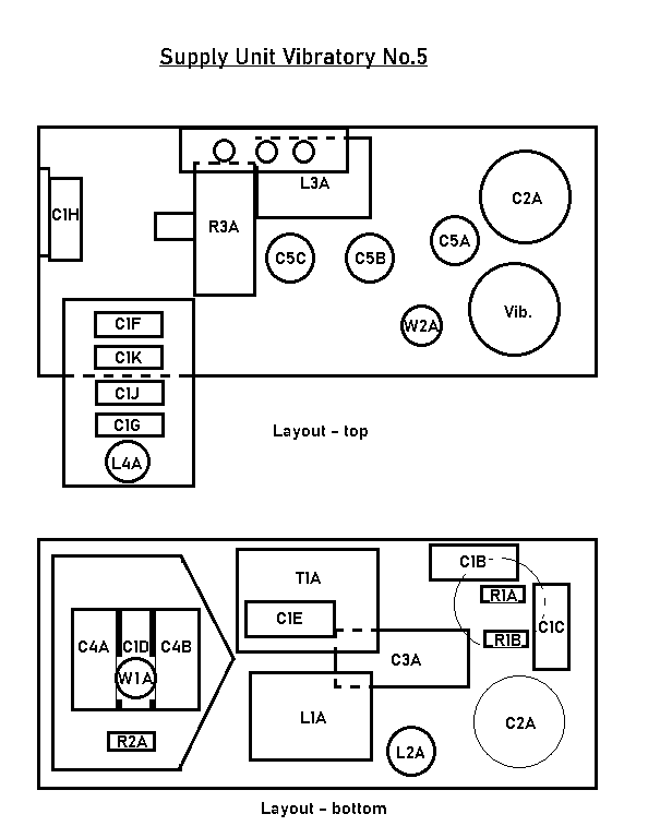
Attention turned to getting the unit working. The case has a welded in chassis plate about 2/3 down from the top upon which most of the components are mounted. Figure 5 shows a diagrammatic layout of the chassis, both above and below. The quite narrow and deep case means working on the unit is a bit difficult. The unit contains several paper and electrolytic capacitors, many of which are fairly critical to correct operation, both from a smoothing and noise filtering point of view, but also to prevent arcing and to suppress transient spikes. The HT electrolytics, C5A, C5B and C5C were tested/reformed, and all reformed satisfactorily. C2A the large 6 V, 1,000 µF supply smoothing capacitor showed virtually zero capacitance when tested. The can was cut using a small hacksaw in the middle of the chassis securing clip, and the contents removed. Two small holes were drilled next to the solder tags, and a modern 1,000 µF capacitor soldered to the tags. The two parts of the capacitor can were mated together and secured together again with the chassis clamp before being secured back on the chassis.
With the main electrolytics sorted it was time to apply power and watch for smoke. A 6 V sealed lead acid battery (SLAB) was connected to the supply terminals while the output voltages were measured. No smoke appeared, but the HT voltage was only about 100 V with no load. The bias supply was also low at about 8 V. First capacitors to come under scrutiny were C1B and C1C, 0.1 µF paper capacitors which together with the two resistors R1A and R1B help suppress arcing of the vibrator contacts. They were both tested by disconnecting one end, but turned out to be absolutely fine, so were reconnected. Next to be checked was C3A, 0.5 µF, a vital capacitor which tunes the transformer and helps reduce the transient spikes from the square wave switching produced by the vibrator. It was seriously leaky, so was removed. The wax was scraped from the ends and the inner “Swiss roll” carefully pushed out. A modern high voltage film replacement, fitted with extended leads was fitted inside the case. A small tightly wound narrow spiral of cardboard was pushed into the ends of the case to make new end supports, before fresh wax was melted over the ends, using the author's usual tool – a hot soldering iron. The capacitor was replaced. The hash filter capacitors C1E, C1J and C1G, all 0.1 µF were disconnected and tested. All were very leaky, and they were removed and re-stuffed similar to C3A. When replaced and the PSU retested, the HT voltage was now some 170-180 V off load – much better.
With the HT side working well, attention turned to the bias supply. C1D was disconnected, tested and found to be OK so was reconnected. The smoothing capacitors, C4A and C4B, both 50 µF were disconnected and reforming attempted, but this failed, with both capacitors being very leaky. They were removed, the plastic insulation film was removed before the clenched over aluminium at one end was carefully sawn off as near to the end as possible, with a small hacksaw, to just remove the clenched over part. The rubber disc was prised out, the capacitor contents removed and a modern replacement soldered to the end tags, and the rubber disc was pushed back into the end. The plastic film was replaced around the capacitors and re-secured with small pieces of clear plastic adhesive tape, before the capacitors were replaced in the supply unit. The supply unit was retested, but still the output voltage was only about 11 V. The selenium rectifier, W1A was disconnected and checked. Reverse resistance was reasonably high, but so was the forward resistance. A modern 1N4002 was wired across the selenium rectifier connections on the underside, with the tiny body of the modern diode hidden between the cooling fins of the selenium one. When retested, the supply then produced about 18 V off load.
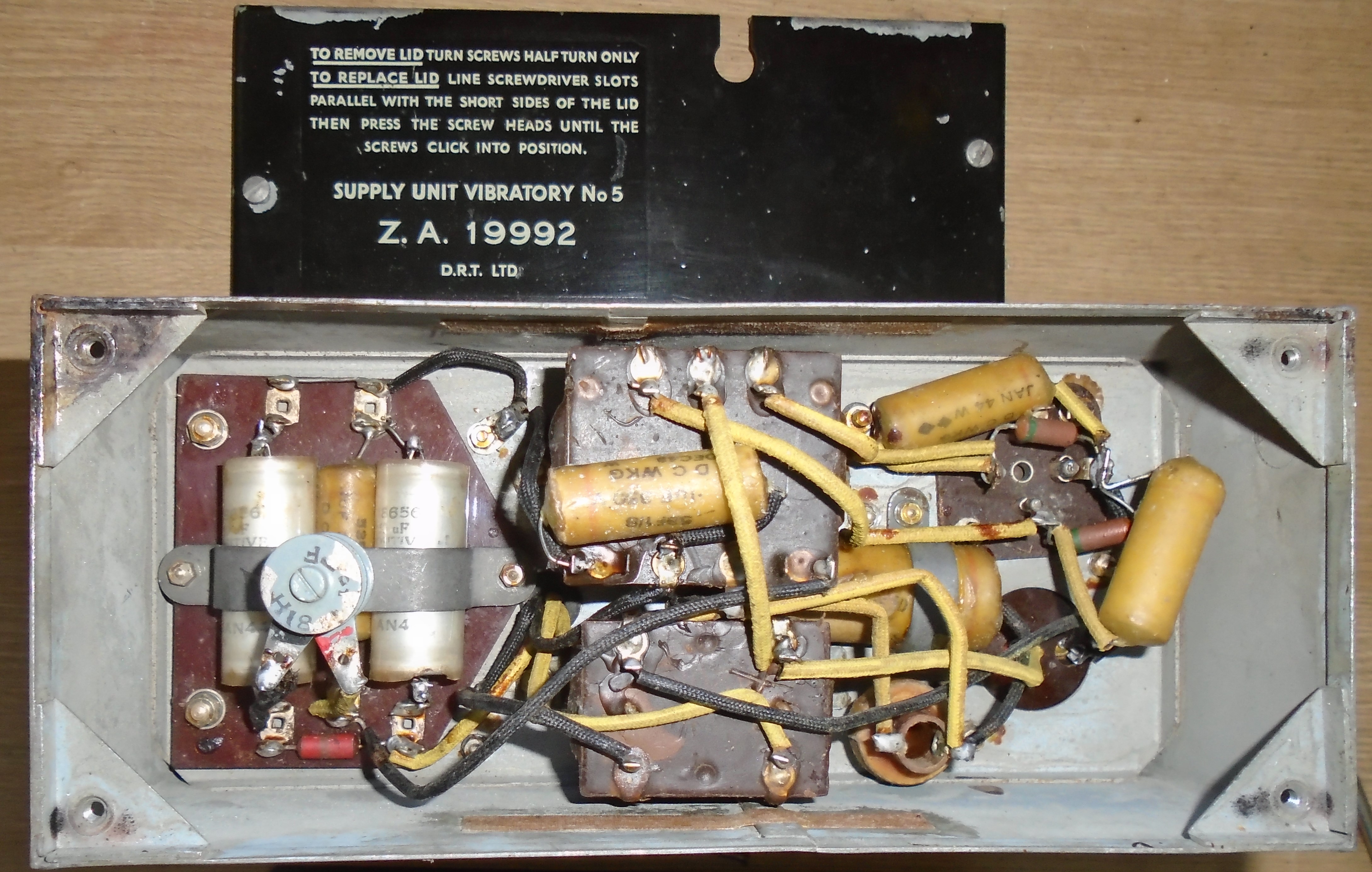
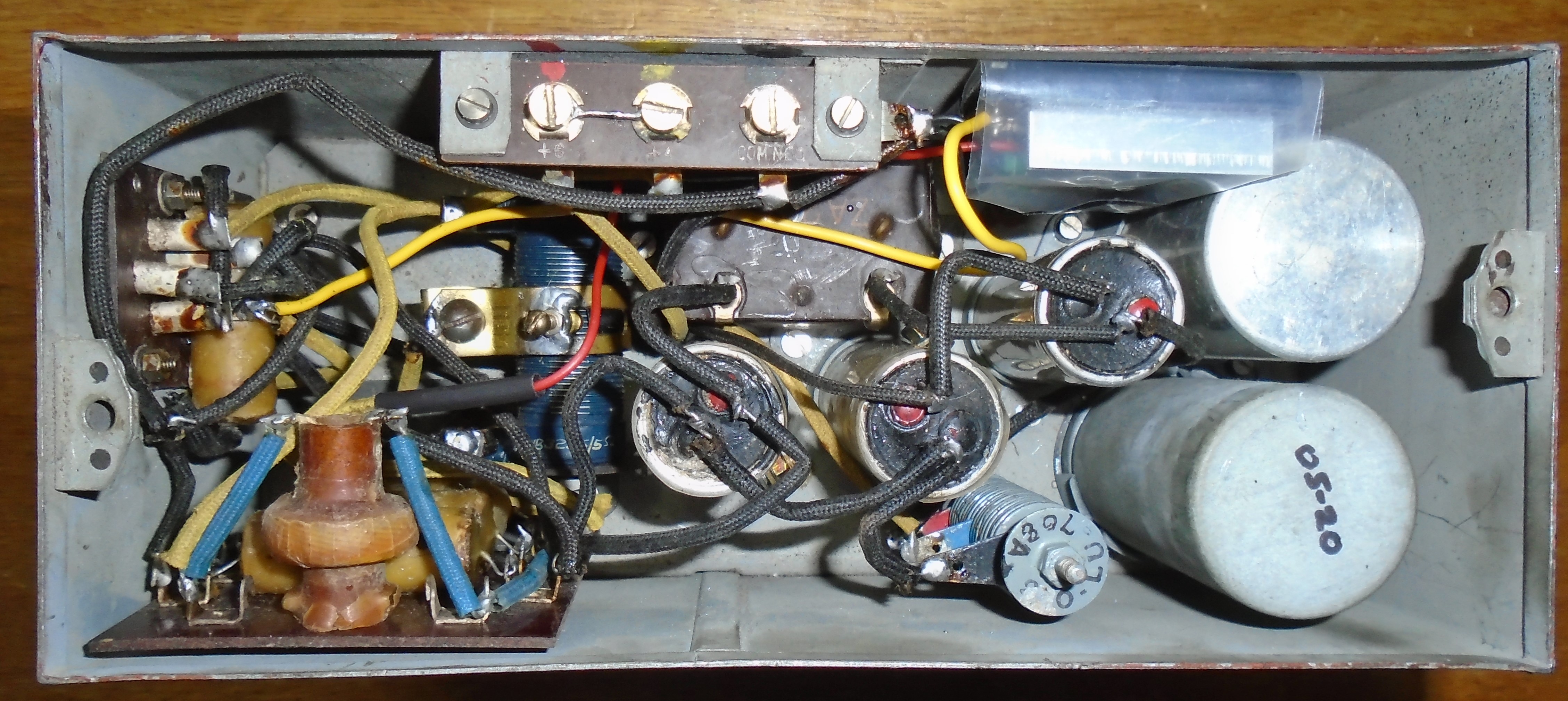
The final problem was the LT supply. Originally, with the three 2 V accumulators, a connection was made at the 4 V point, and a simple resistor or choke used to drop the excess 1 V or so down to 3V for the radio sets. Rather crude, but it obviously worked, though with some voltage variation between transmit and receive. It might be possible to drill and tap a modern sealed lead acid battery at the 4 V point, but it would be a bit hit or miss, probably more the latter. It was decided to cheat. An LM317T variable voltage 1.5 A regulator fitted on a small heat-sink was mounted on a small circuit board together with a couple of resistors and capacitors in the standard regulator circuit, with the resistors adjusted to give 3 V output. The board was wrapped in plastic film and squeezed into a space in the supply unit. The two output LT positive connections to L1A and R3A were disconnected, then connected together and connected to the 3 V output from the regulator board. The disconnected end of L1A was used to provide input power to the regulator board, L1A dropping a small voltage and reducing the dissipation of the LM317T slightly. The end of R3A connected to socket SO2A pin 5 was disconnected and insulated, since pins 4 and 5 on the plug of Connectors, 4 Pt. No.51 used to power the WS38 are connected together, and this would otherwise unnecessarily load the regulator supply. Note this connection is missing on the diagram on Figure 4. Alternatively, the lead to pin 4 on the plug for SO2A could be disconnected, leaving pin 5 to provide the LT– return. Figure 6 shows the under side of the restored supply unit, and Figure 7 shows the top side, with the regulator board inside its PVC wrapping fitted above C5A. A link was fitted between the two left hand screws, where the battery connects, since the 6 V battery supply would now supply the filaments, rather than the separate 4 V tapping. All these wiring modifications are easily reversible.
The power supply unit was now fully operational, but it was missing one part, the battery case.
Battery case.
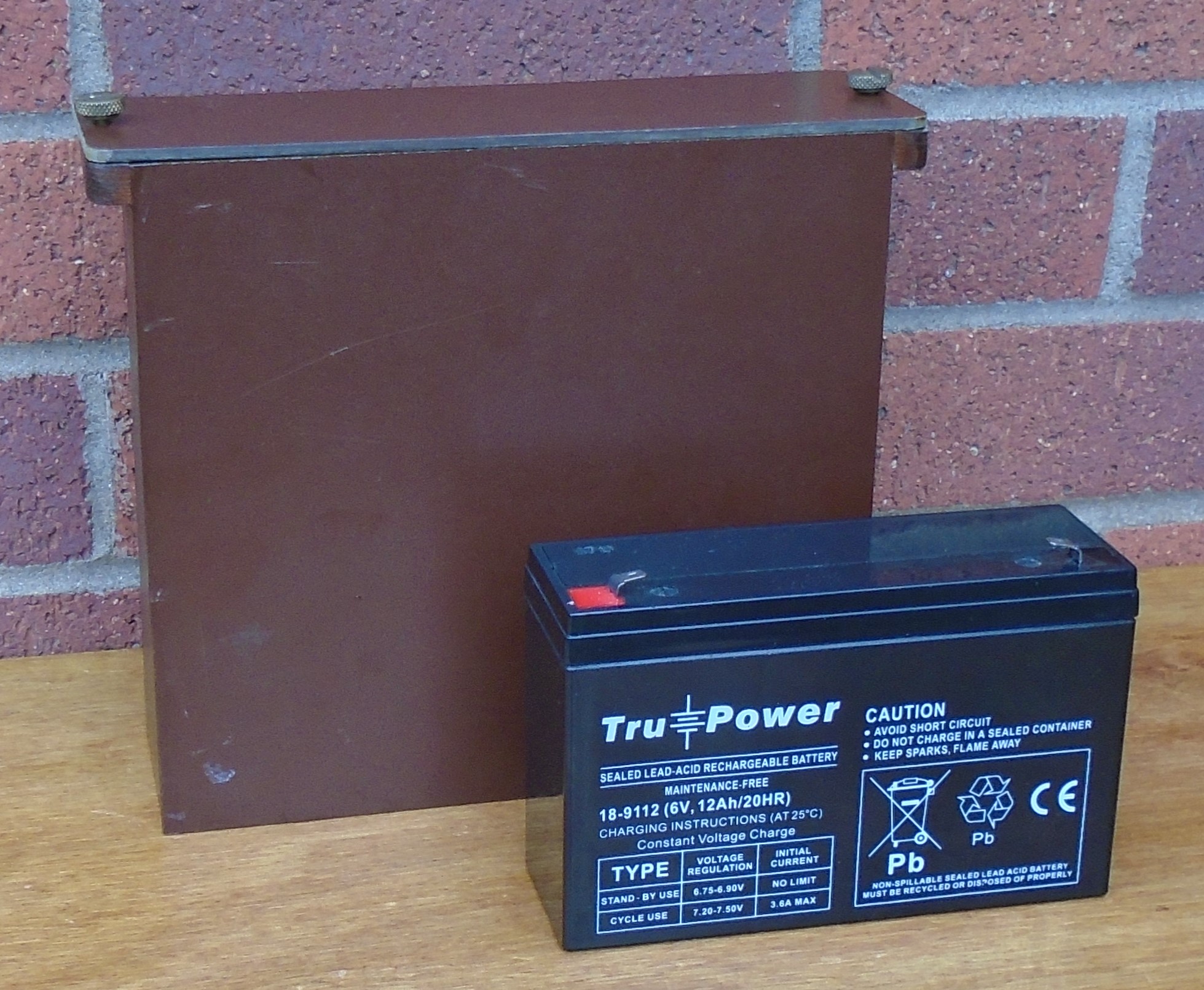
Rather than just leave the battery rattling around in the front of the case, it was decided to make a reproduction battery case to hold it. This would also hid the modern SLAB. The original is described as being made of a moulded plastic material. Looking at close up pictures of an original, [3], it appears to be made of paxolin. The author had a piece of 3mm paxolin, but decided to make the back, bottom and sides with plywood, which is slightly easier to work and glue together, with just the front and top being made from paxolin. A piece of 7mm ply was used for the base, with 3mm ply used for the back and sides. These were glued together with PVA wood glue, supplemented by thin panel pins. The front panel, cut from paxolin was secured to the bottom and sides with epoxy glue. Two “handles” were cut from a square strip of hardwood and glued to the top edge of the sides, to like the original. The top was cut from another piece of paxolin, and two suitable looking thumb screws were found and these were just self tapped down into holes drilled in the top of the handles. The plywood sides, bottom and back were painted with walnut coloured wood stain. This was quite a good match for the dark brown paxolin, and Figure 8 shows the completed case. The internals of the restored and working PSU are shown in Figure 9.
Conclusion.
Restoration of the power supply unit really came down to an electrical renovation. While not in perfect condition, the case was felt to be in good enough condition to be left more or less as was, with just a little rust treatment to prevent further deterioration.
The existing vibrators were restored to working order by fair means or foul, and the necessary capacitors within the supply unit were re-stuffed such that the internal appearance still looked original, apart from the easily reversible cheat used to supply the 3 V supply for the filament supplies. A reproduction battery box was made and serves to hide the modern SLAB.
The supply unit has been tested with the author's WS48 (For which it was not designed) and WS38, and both operated fine, when running from the SLAB. The author was a bit concerned that the 12 V supply, which was only designed to operate as a bias supply, would be able to supply the current necessary to operate the relay in the WS48. This was unfounded. Off load, the voltage was about 18 V. When the transmitter was keyed, the voltage dropped to about 6 V on load, but by then the relay had pulled in, and remained so until de-keyed. The relay consumed about 20 mA, so the bias supply was likely operating at its limit working the relay, but it did so reliably. (Bypassing R2A could also be used to help operate the relay, but this was found unnecessary.) The addition of the modern silicon diode probably helped in this respect. The consumption from the 6 V SLAB by the WS48 was about 1 A on receive, and about 1.7 A on transmit. The on-board hand cranked generator could easily supply this current and more, thus charging the battery at the same time. Providing the full 5 A output from the hand generator, requiring a hand cranking speed of 100 – 110 r.p.m. would certainly exercise the arm muscles.
References.
[1] Electrical and Mechanical Engineering Regulations, Telecommunications K102/1, Power Supply Unit No.5, The Wireless Set 19 Group, Royal Signals, https://www.royalsignals.org.uk/ws.html
[2] The Wireless Set 19 Group, Royal Signals, https://www.royalsignals.org.uk/
[3] The Wireless Set 19 Group, Royal Signals, https://www.royalsignals.org.uk/photos/psu-no5.htm
Click Here to Return to Main Index
![]()
Click here to subscribe to The
Wireless-Set-No19 Group.
Site and all files are copyright © 2004 - 2024 Keith Watt RN, MRCN.